Defrost Vents, Firewall insulation, and more cabin top filler

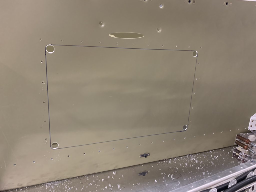
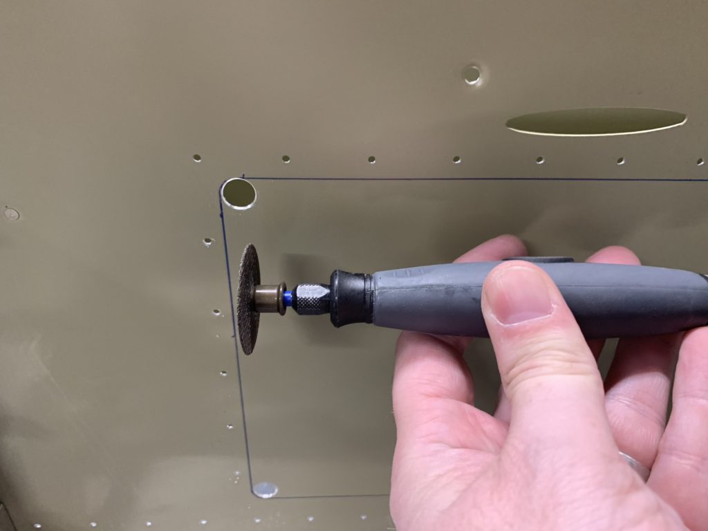
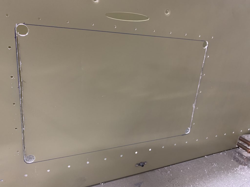
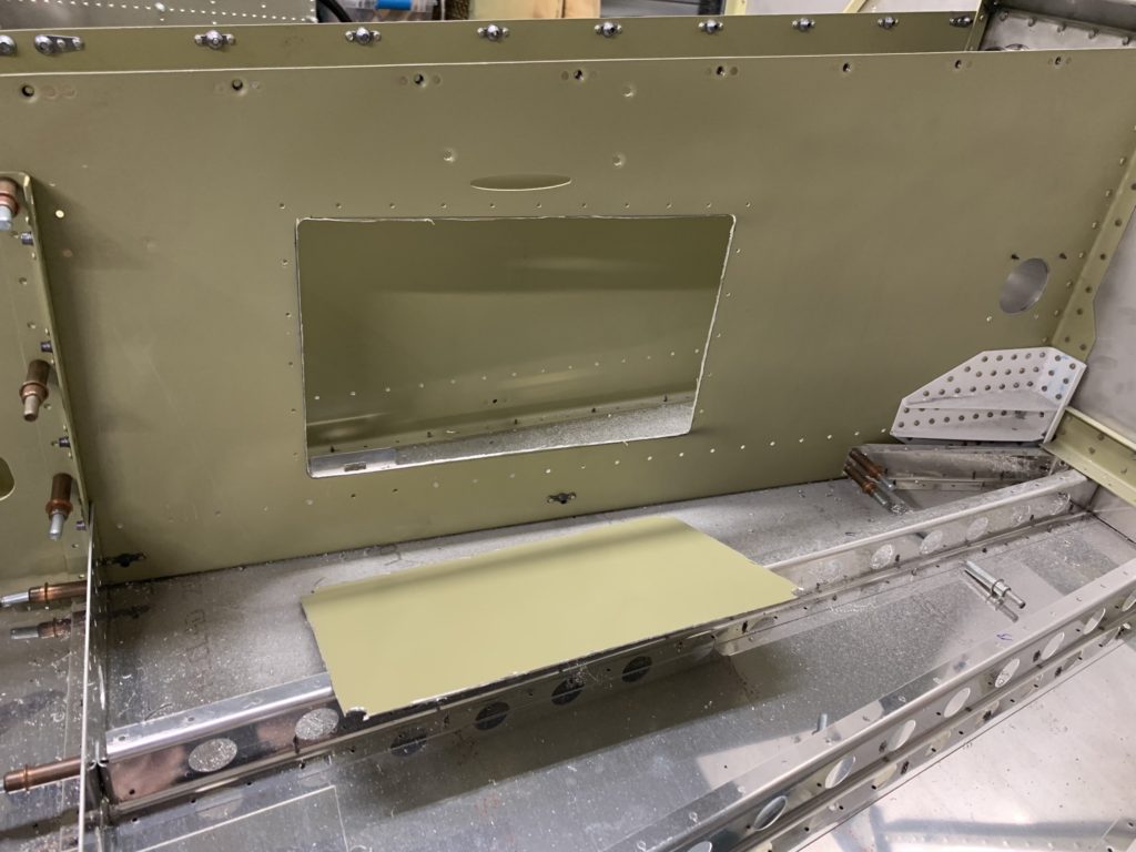
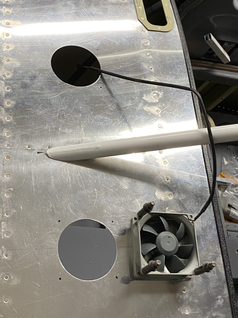
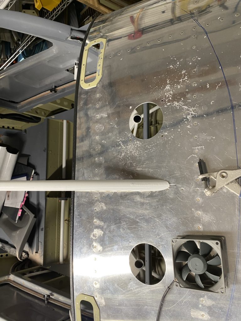
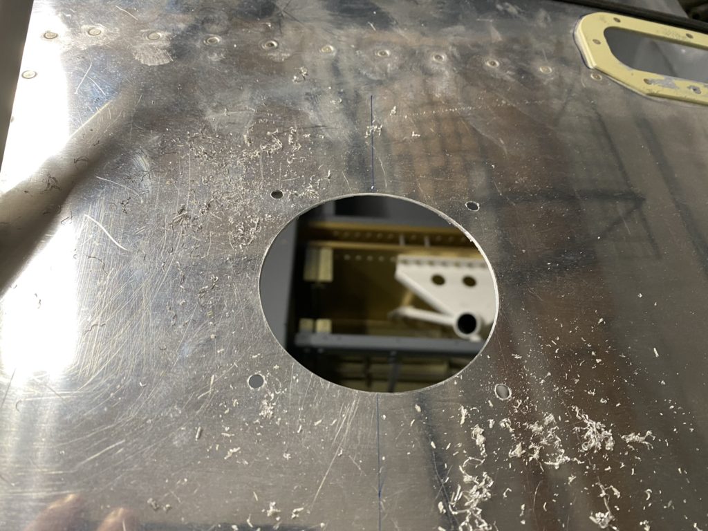
Next item on my to-do list was to cut the holes in the instrument panel for my defrost / avionics fans. I briefly put the windshield on the airframe to mark out where it looks like it will sit to ensure I don’t do something dumb. Next I measure where the hole centers should be off the center rivet line to try to make the fans symmetrical. I then drill a pilot hole at the center mark, then follow with a hole-saw in my cordless drill to make the larger hole. Using the fan as a template, I then mark out where the four mounting holes need to be, then drill one of the holes. I cleco the fan in place from underneath and use the fan as a drill guide to final drill the remaining 3 holes.

I plan to dimple the holes and install countersunk screws to keep the glare shield flush. I think I’m going to use the Aerospot Products glareshield, or possibly the one from SFSport Aviation instead of my original thought of using automotive bed-liner paint.

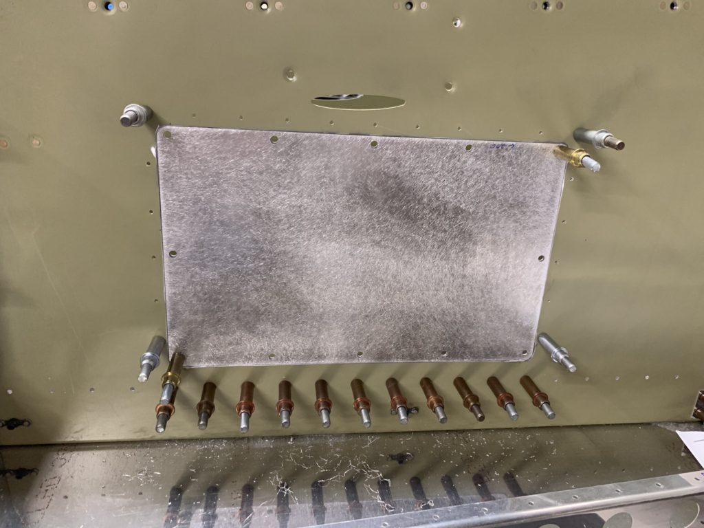
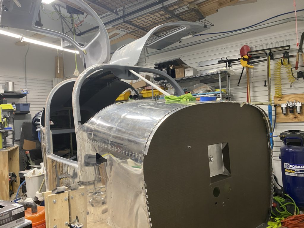
I also decided to change my mind regarding the insulation I am installing on my firewall. Originally I purchased fiberfrax and stainless steel foil and use that as my insulation, but decided to go with lavashield instead. I was thinking the lavashield looked nicer and was easier to install vs the fiberfrax method. Nothing scientific and I’m sure the fiberfrax is superior. I just didn’t like the look of the SS foil over the insulation. Honestly I think the lavashield looks like carbon fiber and at least provides a little insulation value over stock.

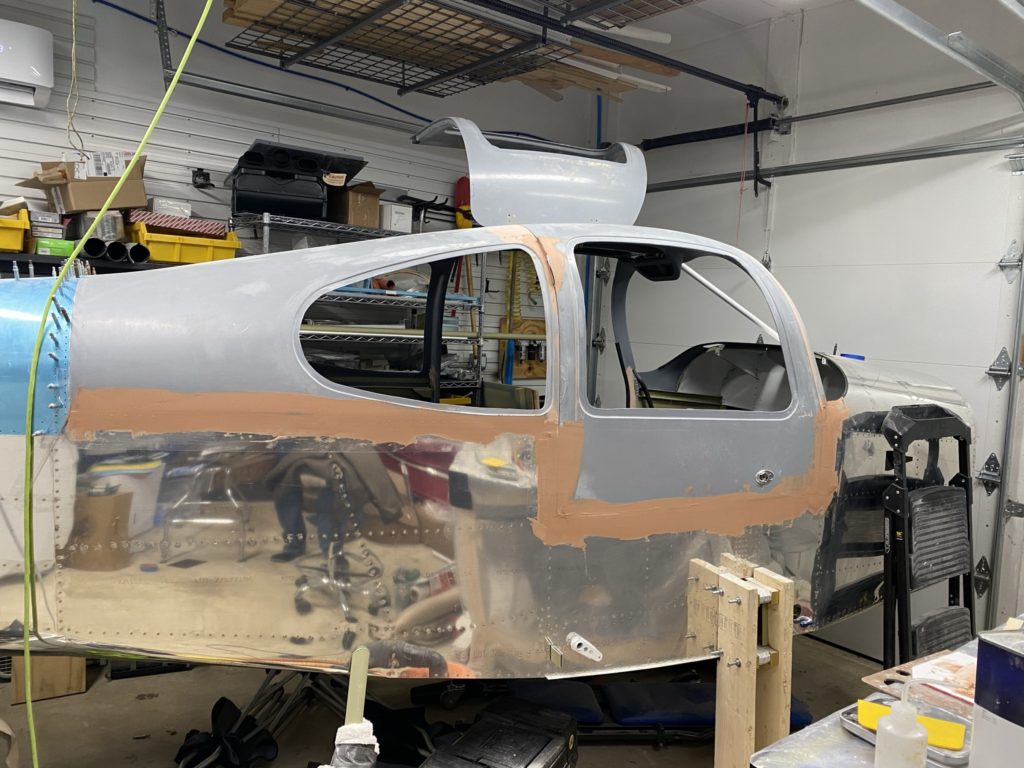
With those items checked off the list, I go back to filler and sanding on the doors and cabin top. I had a very slight gap between the cabin top joggle and the fuse skins that was not due to interference or trimming the cabin top enough, it just didn’t sit completely flush against the skins. I filled this with a little Aeropoxy Light and also decided I was going to cover the blind rivets on the outside of the skin with filler as well to make things look nicer. Again very thankful for the AC/Heat in the garage to make life easier as I sand and blend the cabin top.

FWD Fuse Ribs, BHDS, and Bottom Skins – Part 4

Finishing up section 28 I enlist the help of my friend and his father to help get the last few steps done. Per my last post, they were EXTREMELY helpful in moving my wings to storage, then we all returned to the garage and they helped me knock out the some of the heavy lifting to join the fuse and move it to the cradle.

Before I got my camera rolling, we finished riveting the forward bottom skin to the tunnel. Next we installed the forward spar and installed all the bolts called out in the plans. (PROTIP: Now is the time to torque and apply torque seal to all your bolts on both the forward and rear spars! Also jump ahead to Section 44-2 and install the K-1100-08 nutplate between the spars now. )

One item to note is that I decided NOT to install the flowscan or fuel filter brackets as I am expecting to install an EFII system. I’ll go into this system in a future post as I have more information that I can share.

With both halves ready, we then joined the forward and rear halves and began to install some temporary bolts (Home Depot brand. I’m saving the AN hardware for installing the wings!). With the halves bolted together, we easily move the fuse to the cradle. Plenty of room now that the wings are in storage!

I believe it was at this point I realized that I hadn’t torqued down my bolts, or installed the nutplate. Ended up getting a neighbor to help me move the fuse back to the tables to fix my issue. Then they helped me move it back to the cradle once I fixed my minor issues.

Once on the cradle, I began to spend my time crawling on the floor to install clecos and taping flush rivets into place. My wife who is now becoming an expert with flush rivets, helped me over the course of a few weeks to rivet the skins to the spars. I will say that this was not an easy task. I used just about every bucking bar I had, and even then was not happy with some of the results. Honestly for the “hard to reach” rivets the BEST results were obtained with indirect riveting. (Similar to what I did for the Elevator – Part 9). I had a purchased this bucking bar from YardStore to get into really tight spots. Basically use a backrivet bucking bar on the skin side, and the angle bar on the shop head. Then use the rivet gun on the angle bar to indirectly set the rivet. It sounds funky, but it does work.

With the “Hard” stuff done, I move onto fabricating the seat pans. Cutting the angle aluminum I realize that I made a mental error and cut one too short. Another example of why ordering a few extra sticks of angle aluminum with your wings/fuse is such a good idea! Poor Jason Ellis learned that the hard way 🙁

Beyond measuring correctly, everything else goes together pretty easily. Just have to mark everything as L or R and make sure you visualize how everything goes together (mirror of each other).

Once those are done, it’s onto the landing gear assembly. My right side landing gear needed me to modify the bulkheads a little to get everything to fit without any interference. I took my time to file and deburr with scotchbright. Didn’t want to remove too much material!

With everything fitting correctly, I drill the last few holes and close out the chapter.

FWD Fuse Ribs, BHDS, and Bottom Skins – Part 3

Continuing on with Section 28, I had an EPIC priming day and got all of the outstanding items painted (including the last of my wing skins!)

With everything primed, I begin to do the final assembly on all the ribs and bulkheads for the forward fuselage. First step is dimpling all of the parts that will have flush head rivets, then installing rivets in all of the sub-components.

I then pull out my trusty DRDT-2 and begin to dimple the bottom wing skins (after I remove the plastic and deburr). Didn’t catch the larger skin being dimpled, but it’s in the background of my timelapse). I’m basically out of room to move in the garage so I’m about to have a moving day to get the wings into storage.

I then complete the dimpling of all of the other components (making sure I take the time to understand what does and does not get dimpled). Then it’s on to prepping the bottom skin so I can back rivet the ribs on. This was very easy and looks great once done. Even got a little assistance from my oldest while I was working on this part.

I decided to order some firewall sealant from skygeek vs using proseal to seal between the skin and the firewall. It looks very much like proseal in the tube, but has a very different consistency when applied to the surfaces. Almost has a foam type of quality to it? Anyway, with the sealant applied, I quickly squeeze those rivets then start to rivet the tunnel to the bottom skins.

My attempts to back-rivet these parts did not work as planned and I ended up drilling these rivets out I’ll need to call in some favors to help set these rivets before I join the fuse and hopefully move it to the cradle.

FWD Fuse Ribs, BHDS, and Bottom Skins – Part 2

Continuing to work on Chapter 28, I begin by pulling the plastic off the interior of the forward bottom skin. After I figure out the rib orientation, I cleco all the parts together. Then adding the bulkheads and system brackets, final drilling per the plans as I progressed.

Before I attached the firewall and tunnel to the skins, I had to go back and rivet on the Rudder Pedal brace that I didn’t do in the previous chapter. Took a try or two before I was able to successfully get the rivets installed to my standards.

Next I join the firewall and tunnel assembly to the skins and then stand the whole section on the firewall (with wood scrap under the firewall to prevent the flanges from bending!). Gracefully climbing onto the workbench, I then final drill all of the remaining holes common to the firewall, tunnel, and bottom skin.

Then, the whole assembly is back on the skin (technically the celcos that are in the skin) so I can final drill the firewall to ribs. Small side note, I had already dimpled the firewall where it attaches to the ribs, but not the ribs. In hind-sight I could have waited to dimple this section of the firewall till later and used my squeezer. Hindsight is 20/20. This was obvious to me once I attempted to install the floor pans, so I ended up taking the firewall off and dimpling those ribs to match to ensure everything lined up correctly. I didn’t end up capturing this swearing session on video but it did happen 🙂 Once re-assembled, the floor pans went in fairly easily (they are tight and almost a friction fit).

Then it’s on to installing the forward spar. I put some cribbing under the skins to support the spar as it is quite heavy. Match drill the holes called out in the plans, and install the temporary bolts to hold everything together. Not too difficult.

After some off-camera shuffling of items in the garage, I have my wife assist me in lowering the aft fuselage onto a workbench and I being the process of the initial mating of the forward and aft fuselage. Super exciting as you get these somewhat large parts mated together. I had to use lumber to lift the aft end of the fuse to allow the spar bolt holes to line up enough to get my Home Depot Aviation Department temporary bolts to fit. I bought 2 sets of temporary bolts. One set to for just this step. The other will be sanded down into bolt alignment pins for later in the build. I’m only going to install the “final” bolts and nuts once as I don’t want to damage them / purchase a second set if I don’t have to.

With everything connected, I did all the final drilling called out in the plans, crawled between the tables to final drill the skin to spar holes, then had to take the whole forward fuse apart so I could deburr and prime.

Forward Fuse tunnel access panel

So as I began to think ahead and read mods that others had done / suggested, I came across a number of posts talking about the need for an access panel into the forward fuse tunnel so you can easily get access to fuel filters for condition inspections and maintenance. I thought this made a lot of sense and decided that I also needed to include this mod in my build.

Decided to order two of the kits from Airward, Inc. This was really just some pre-cut sheet metal as well as a handful of hardware (rivets, nutplates, and screws) to install the tunnel access panel. I’m sure I could have created one on my own, but figured the pre-cut kit would have better cut lines, etc.

Initially I have only installed one of the access panels on the passenger side of the tunnel. I have seen plenty of others that installed both, I’m trying to decide if I really need access from both sides yet.

The instructions are mostly straightforward. It was slightly unclear how far forward / aft to install. I just made a judgement call and moved ahead. Also I noticed that the pre-drilled holes on the doubler (part of the reason I purchased this kit) didn’t fully align with the pre-drilled holes from Vans. 🙁 As I final-drilled, some of my holes are now out of round on the doubler. This isn’t a huge problem as I’m going to be installing some angle aluminum behind the doubler at this location for my Fuel system install.

With the doubler plate match drilled along the bottom row of pre-drilled holes, I then match drill the remaining #40 holes around the outside of the doubler. Then, you drill the four corner screw holes, cleco the access panel into those holes and draw the access panel outline. Then it’s a matter of using a strep drill and your tool of choice to cut out the access panel hole.

Clean up the edges, cleco the doubler in place and test fit the access panel. This will take a little bit of trial and error so your access panel opening matches the access panel. Once you think you have it looking good, then install the hardware on the doubler for the nutplates, Clean and prime everything, then install the doubler (except the for bottom row of rivets until you are ready to install the cabin floor. )