Air Conditioner Scoop

With the next few steps in the plans having me rivet down the rear floor and seat panels, I realized that now was the time to install the Air Conditioner scoop. The kit for the AirFlow systems includes riv-nuts, however I have heard enough complaints regarding riv-nuts that I decided that since I have access I’m going to just install nutplates.

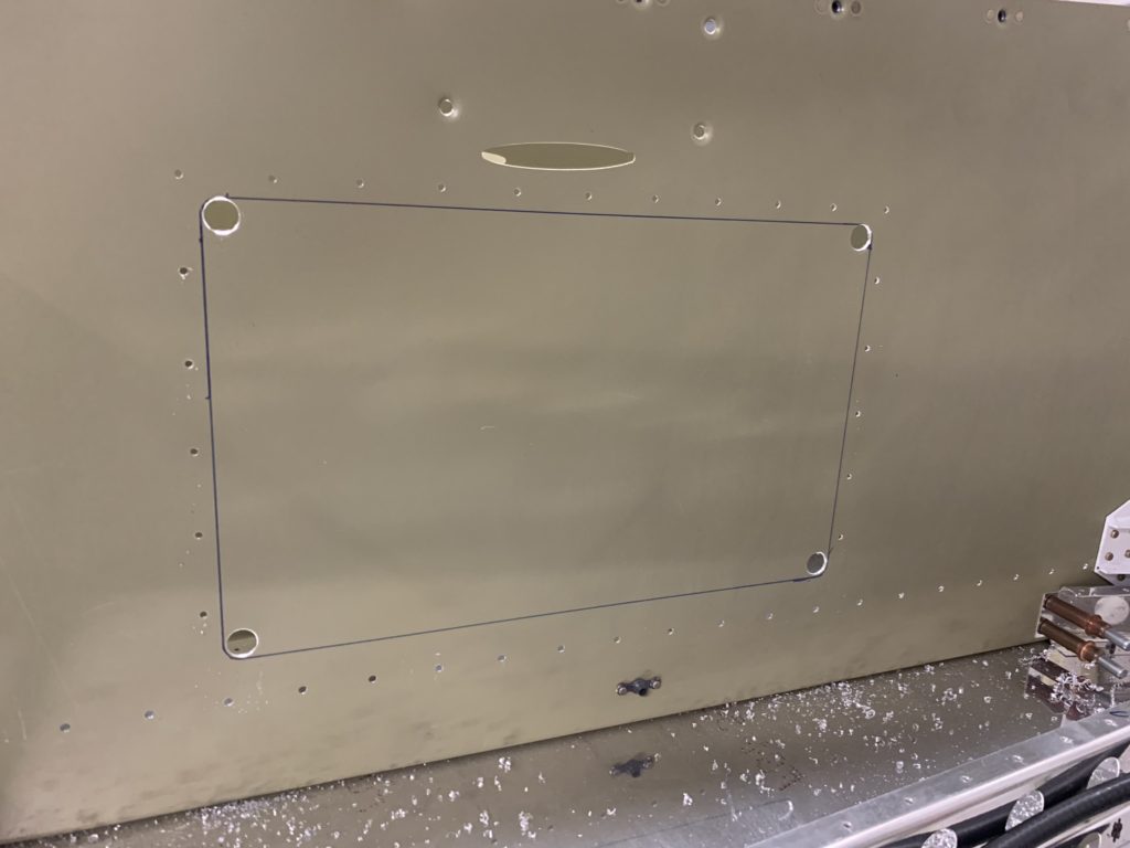
The first step is to mark the center line of the air scoop as well as the center line of the aircraft as you really want this to be perfectly centered. I spend a lot of time making a lot of measurements to try to make sure I get this correct. I’ll just say that the reflections from the skin and how I have my project sitting in my garage really did make this a difficult task as what I was seeing vs what my measurements were telling me did not agree.

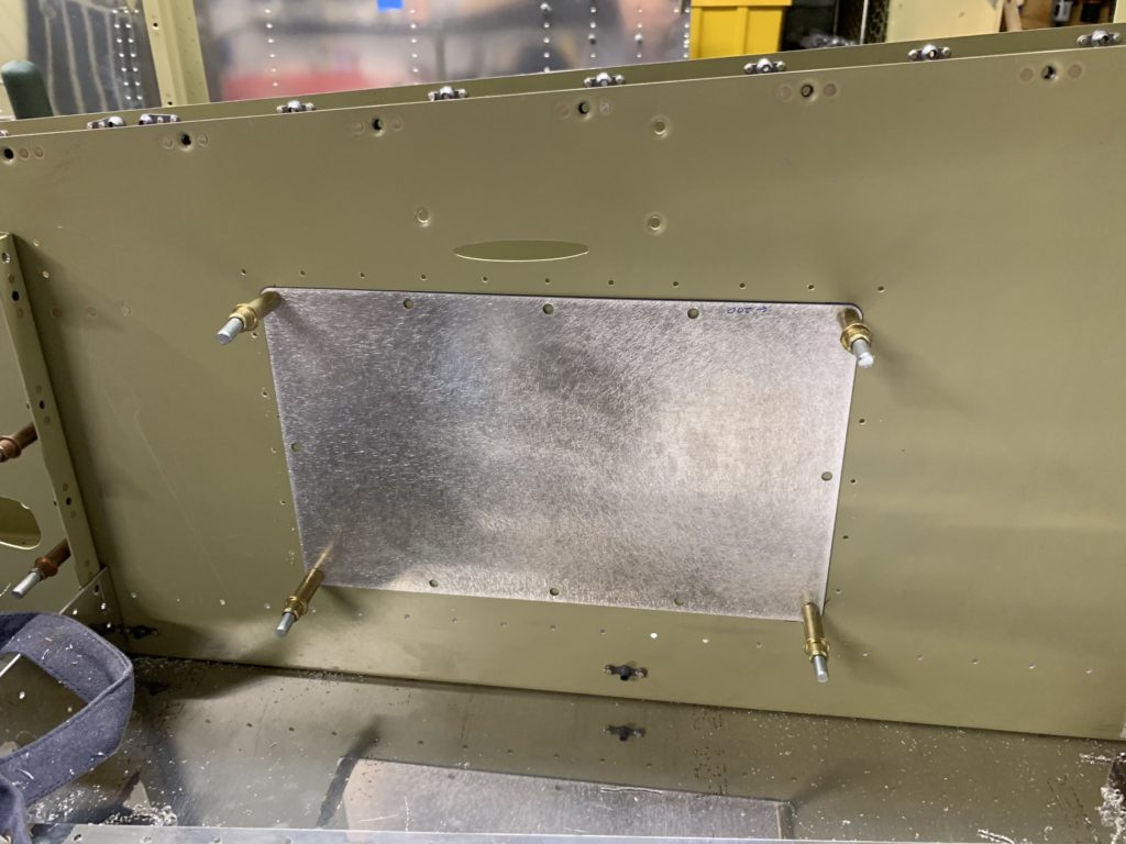
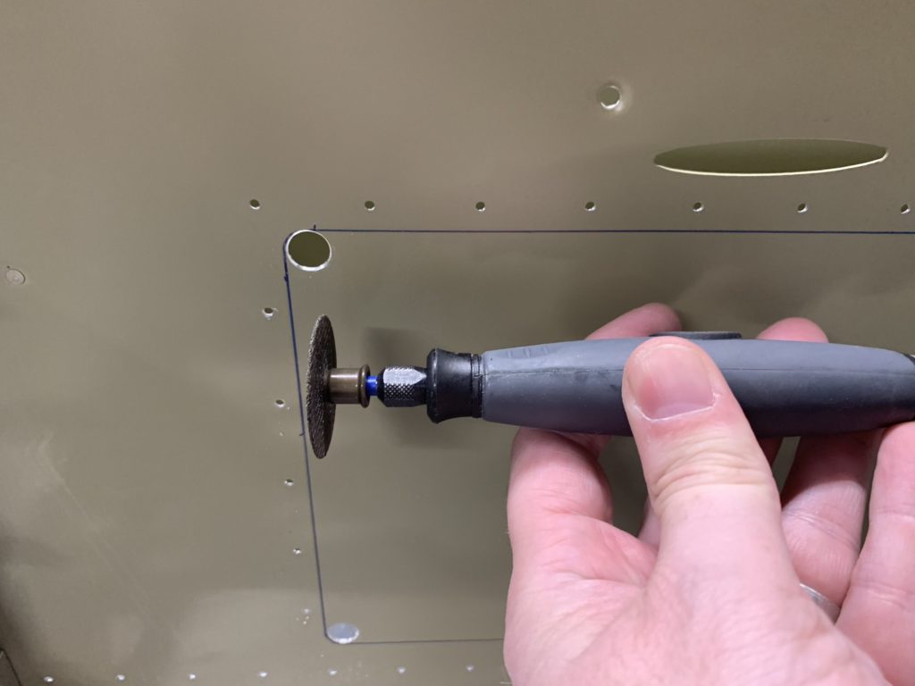
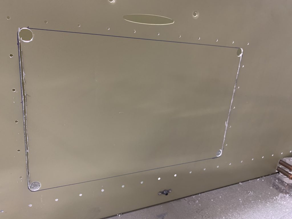
I used making tape on the fuselage, a cardboard template I created from the scoop itself, as well as installing masking tape from down the length of the scoop to help me mark the centerline. I finally got to the point where I had to make the first hole in the skin. With the scoop clecoed to the skin, I drilled all screw holes and avoided drilling any of the spars.

Only after I did this did I read that someone used a sheet of acrylic to template the scoop so they could see where they were drilling. That was very smart and I wish I thought of it. Something to remember in the future I guess.

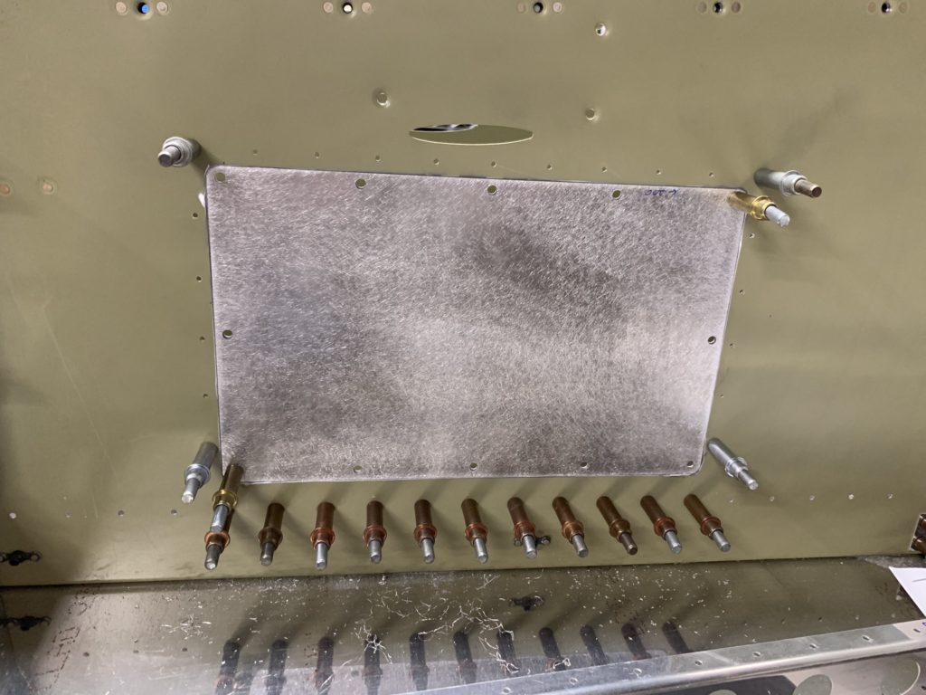
With all of the holes drilled, I used my nutplate jig to drill all the #40 holes for the nutplates. I then had to enlist my daughters to help me dimple the holes using the close quaters dimple tool. This is the dimple set that has a hole in the center and copper rods and nails to set the dimple.

Pro-tip: I found that the Stainless Finishing nails from Home depot were perfect vs the nails included in the tool. I ended up ruining a set when I pulled a nail though the dimple dies and had to get a replacement set.

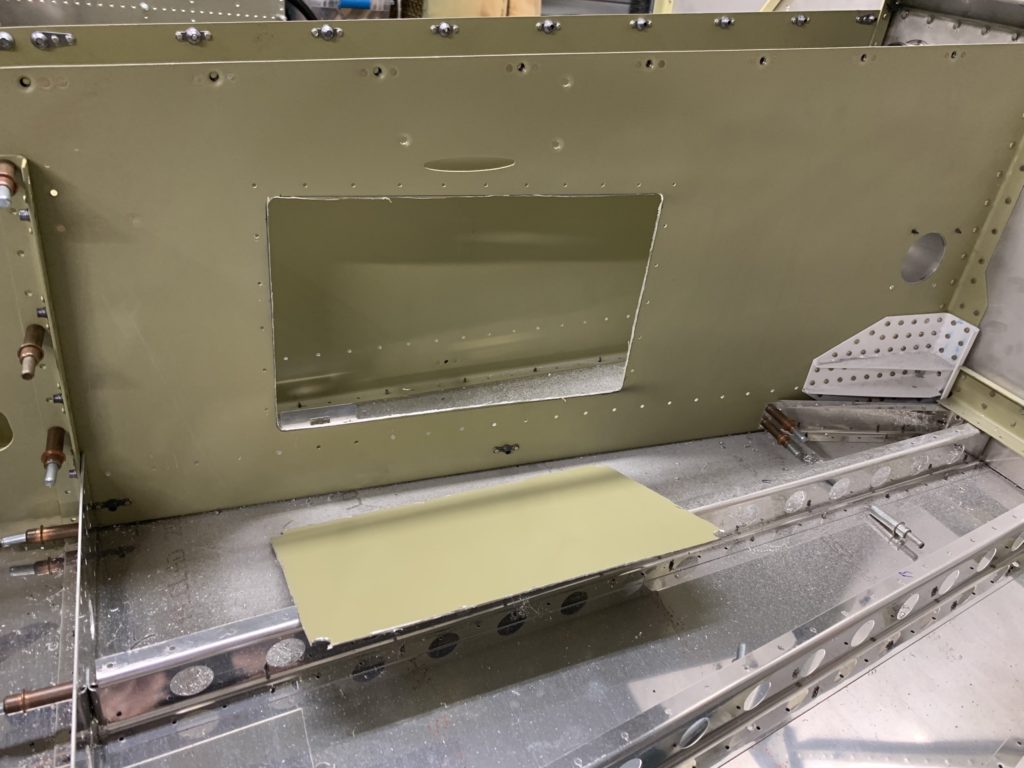
With all the holes dimpled, I had my wife assist with back riveting the nutplates. After installing the scoop to make sure everything looked good, I needed to drill the holes for the radiator (condenser) into the center tunnel. This made a template and drilled the holes into the center tunnel. The instructions don’t tell you that you need to put a doubler around these holes, but I’m thinking that installing one may be a good idea. It’s on my list of things to do “later”

With the scoop installed, I putting the AC stuff off to the side until I get the baggage bulkhead installed At least I can store the scoop on the bottom of the plane for now so it’s out of my way.

Rudder Pedals

I was getting a little frustrated with the overall progress of the build and wanted to do something to help with my motivation. I decided that installing the rudder pedals (Control Approach upgrade) would both make me happy and was something that wouldn’t have an impact on the build process.

The rudder pedals are in my opinion a huge upgrade both visually and functionally. Dealing with Paul was very pleasant as I was not in any rush when I ordered them. I honestly was the biggest holdup as I didn’t have my master cylinders before he was ready to ship, so he ended up sending me the pedals with a set of his master cylinders and I just shipped him the ones I got from Vans in my Fuse kit when it finally arrived. Nothing but great things to say about Paul.

Setup of the pedals was SUPER easy. There are no instructions that come with them, but it’s pretty easy to figure out on your own. Connect the two sets of pedals in the center and screw in the four bolts. Only new skill I had to figure out was how to do the safety wire on the bolts. Quick refresher from YouTube and I was good to go. (Think they turned out pretty well).

The only thing that I don’t like about them at the moment is they are not compatible with the aerosport rudder trim system. Paul has said he is working on something, so fingers crossed that may become a thing.

Forward Fuse tunnel access panel

So as I began to think ahead and read mods that others had done / suggested, I came across a number of posts talking about the need for an access panel into the forward fuse tunnel so you can easily get access to fuel filters for condition inspections and maintenance. I thought this made a lot of sense and decided that I also needed to include this mod in my build.

Decided to order two of the kits from Airward, Inc. This was really just some pre-cut sheet metal as well as a handful of hardware (rivets, nutplates, and screws) to install the tunnel access panel. I’m sure I could have created one on my own, but figured the pre-cut kit would have better cut lines, etc.

Initially I have only installed one of the access panels on the passenger side of the tunnel. I have seen plenty of others that installed both, I’m trying to decide if I really need access from both sides yet.

The instructions are mostly straightforward. It was slightly unclear how far forward / aft to install. I just made a judgement call and moved ahead. Also I noticed that the pre-drilled holes on the doubler (part of the reason I purchased this kit) didn’t fully align with the pre-drilled holes from Vans. 🙁 As I final-drilled, some of my holes are now out of round on the doubler. This isn’t a huge problem as I’m going to be installing some angle aluminum behind the doubler at this location for my Fuel system install.

With the doubler plate match drilled along the bottom row of pre-drilled holes, I then match drill the remaining #40 holes around the outside of the doubler. Then, you drill the four corner screw holes, cleco the access panel into those holes and draw the access panel outline. Then it’s a matter of using a strep drill and your tool of choice to cut out the access panel hole.

Clean up the edges, cleco the doubler in place and test fit the access panel. This will take a little bit of trial and error so your access panel opening matches the access panel. Once you think you have it looking good, then install the hardware on the doubler for the nutplates, Clean and prime everything, then install the doubler (except the for bottom row of rivets until you are ready to install the cabin floor. )

Air Conditioning – change of heart

Well, not how I really planned for things to go based on my last post regarding an AC system. Let me first say that this summer was hot. Hotter than normal and for the few flights I did end up taking, and it was fairly miserable when we were taxing and down low.

One of the big things I’m trying to keep in mind is the comfort of my family. I don’t mind getting a little sweaty as I try to climb to cooler weather, however once my wife and girls start feeling hot and uncomfortable, the will absolutely decide that they don’t want to go flying with me. OR they will only go flying when the weather “perfect”. Not a great situation to be in.

So with this in mind, I did more research, reached out to who I consider the two major vendors of A/C systems, and started to plan how I would proceed. After a lot of consideration, I have decided to purchase the system from Airflow Systems. This is a belt-driven system with an air-scoop on the bottom of the plane for the condenser. After a few conversations with Bill from AirFlow Systems, I decided that I would purchase the system now, while I’m still working on the fuselage and have full access to the floors to help plan cable routing.

Looking forward to getting the AC kit so I can get a better idea of installation, hose routing, and other items. I know there are lots of good blog posts out the and photos from others, but sometimes having the items in hand make it easier for me to fully understand how it all goes together.

Air Conditioner

So I have been going back and forth on this topic personally a lot over the last year or so. Initially I was of the opinion that this was a MUST for me for the comfort of my family. This has lead me to reading a number of blog entries from other builders on how they installed their systems and the different options out there.

Currently I’m following three systems (or two depending on how you look at it). Air-Flow systems, Flightline AC, and South Florida Sport Aviation (repackaged Air-Flow systems with overhead console). The Air-Flow / SF Sport Aviation system uses a condenser scoop that sits on the belly of the aircraft that looks like a P-51 scoop, while the Flightline system is contained in the tailcone just behind the baggage bulkhead.

I was personally thinking of going with the Air-Flow system package as I liked the idea of the condenser sitting outside of the aircraft. It looked slick and installation didn’t seem to be too challenging. It also didn’t have the issues of routing air for the condenser through the tailcone and freed up some space in the tail.

The downsides to all of this is that the AC is really only there to help on the ground, or down low on a really hot day. As I said I thought this was a MUST for my family, but starting to change my mind. In addition to it’s limited benefit, it is a complex system in general, with modifications needed Firewall forward, as well as in the fuselage. Extra hoses / cables that need to be routed, and additional weight to an aircraft. It is also an additional cost in time and budget.

As I submit my final payment for my fuselage and feel my bank account lighten, I am starting to plan out some of the additional items that I will need to order throughout the year for this project. Since an A/C is much easier to install when working on the fuse, this item is highly visible on my list of things that may need a decision in the near future. At the moment, I’m of the opinion that an AC is a luxury item that is not needed in my situation. With the exception of possibly going to Oshkosh, I shouldn’t be in a position where I will have an extended ground taxi in extreme heat / sun.