While the wings seemed to just take forever, the side skins of the fuse made me question my life choices. This chapter just took forever for me to complete. Between family, work, and the desire to keep my sanity I found that I was just dragging my feet on this chapter for many reasons.
Looking back, most of my delays were trying to find time to get someone to help me rivet in areas where I just couldn’t do it myself. As I have said before, I don’t have many friends that are into aviation and those that are really don’t want to help me rivet unless I desperate. (I think they are scared that if they do it wrong my airplane will fall out of the sky one day! LOL. ) My other default choice is my wife, however she also has her limits on what she is willing and capable of doing.
With the challenges to get helpers scheduled, I ended up jumping around quite a bit. I’ll post updates on those shortly, however the main point of this update is to celebrate that I completed Chapter 29. The takeaway is, keep working at it. While it seems to take forever, there is light at the end of the tunnel.
One thing I’m going to start doing is posting more details about upgrades and mods. I have been spending a lot of time looking ahead in the project and trying to make some decisions. Hopefully I’m not getting too far ahead of myself, but thinking ahead will help prevent some pain later on. As I mentioned in my New Years post, I did order the Finishing kit, as well as a smattering of other items. Hopefully I’ll start getting some of those goodies in the near future.
The timelapse for the end of this chapter isn’t complete as I just didn’t have it in me to video everything. But it does show I was doing most of the work myself. 🙂
Returning to our adventures in Section 29, I decide to skip to the end of the section and assemble the rear vents. This is very straightforward and requires a little cutting of parts into their individual pieces followed by some light sanding / deburring. Then it’s on to clecoing them to the skin and match drilling. I finish up this minor detour by countersinking the parts as detailed in the plans.
With that completed, I go back to bending skins. The forward skins are a little more complicated as you don’t have the same advantage of using the holes in the edge of the side skin you did on the aft skins. This means you are free-clamping the aluminum angle in place and just using pressure to keep everything lined up. There is a small note of caution in the plans to make sure the clamps don’t crash into the skins. It’s real, and it’s easy to do. At least that’s what a friend told me. 😒
After doing the dance of bending a little, test fitting, bending some more, I finally have the forward skins appropriately bent. I will note that the skins are not a perfect bend. I.E. they are close and as you install the clecos they do pull in the last 1/4″-1/8″ or so to be flush. My opinion is this is fine. I have seen others struggling to get the bend perfect. If this was necessary Vans would have sent the part pre-bent. Just make sure everything lines up correctly.
With the skins done (mostly), then I bend the two small lower fuse channel clips. Easy to do with a vice and a few hits from a mallet. I then pull out all of the remaining understructure that will support the forward skins and install them on the fuse. With these parts in place, the skins go back on and I can begin the process of match drilling all the holes.
The only challenge at this point was match drilling into the steel firewall brackets. As I was getting everything set, I noticed that the firewall brackets are not perfectly aligned with the fuse channels. Also drilling through the steel parts takes a little more “umph” and something to push against the steel bracket. I used some scrap wood to drill the holes in the upper fuse bracket, but had to enlist the assistance of my wife to drill the holes on the face of the bottom bracket.
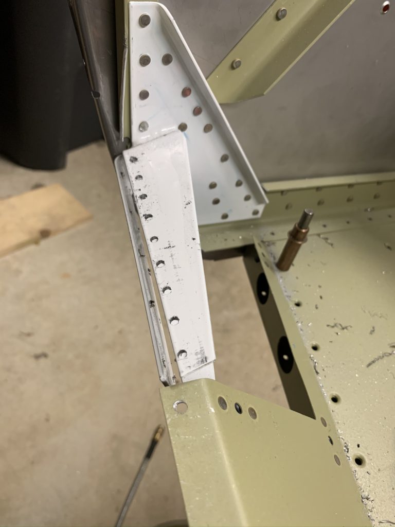
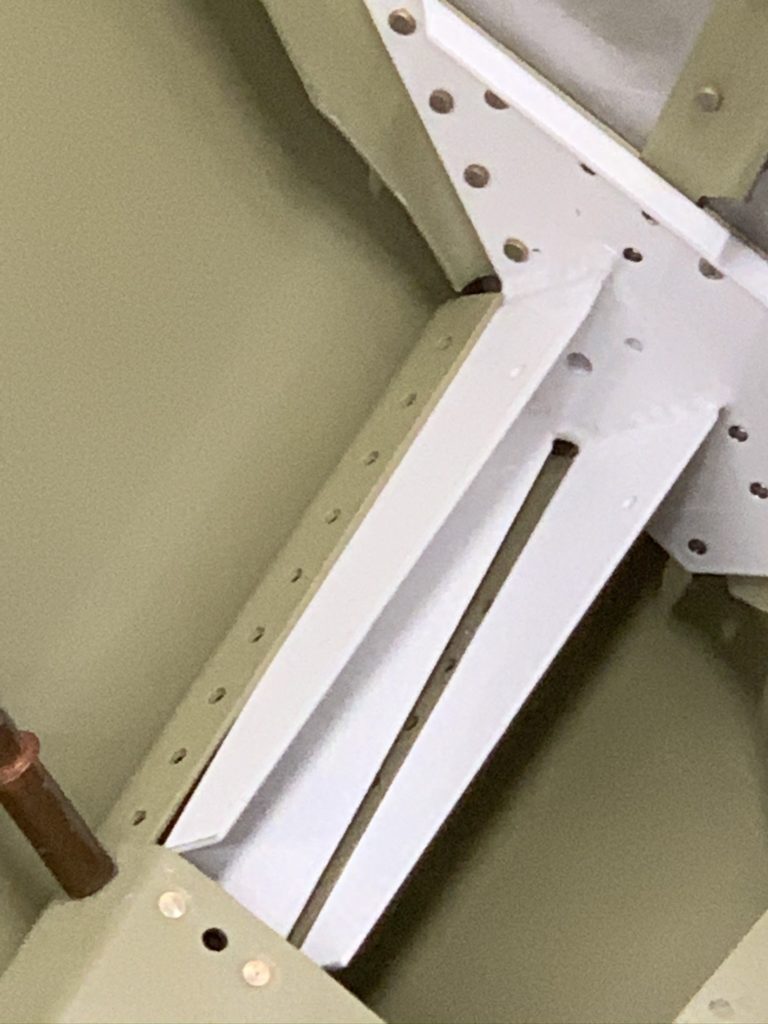
With the longeron and the understructure match drilled, the skin comes off again. Now I have more access to drill all the remaining holes in the firewall brackets. This is where edge distance seems to be the biggest concern. I didn’t initially use clamps to pull the brackets into perfect alignment, and for the first three brackets, all worked perfectly. The last bracket however was just a little off and I was not happy with my edge distance.
Original Bracket
Poor edge distance
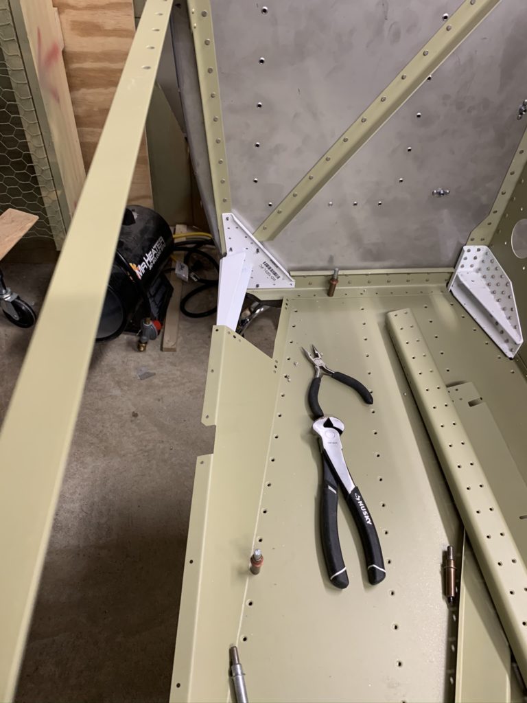
Remove the original bracket
Hmm. New bracket looks off
That’s not going to work.
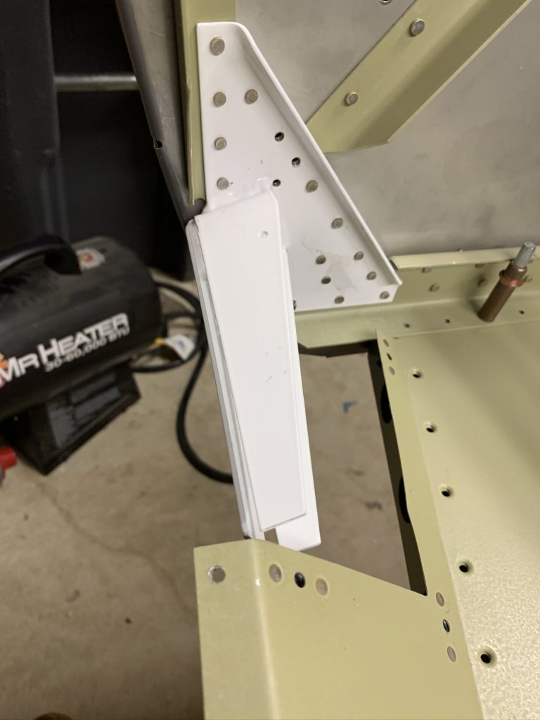
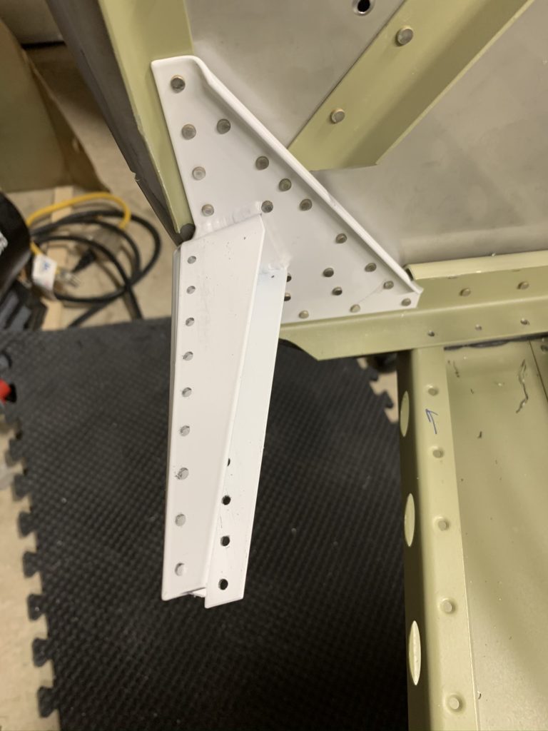
Vans sent a free replacement. Looks better!
Man, that looks MUCH better!
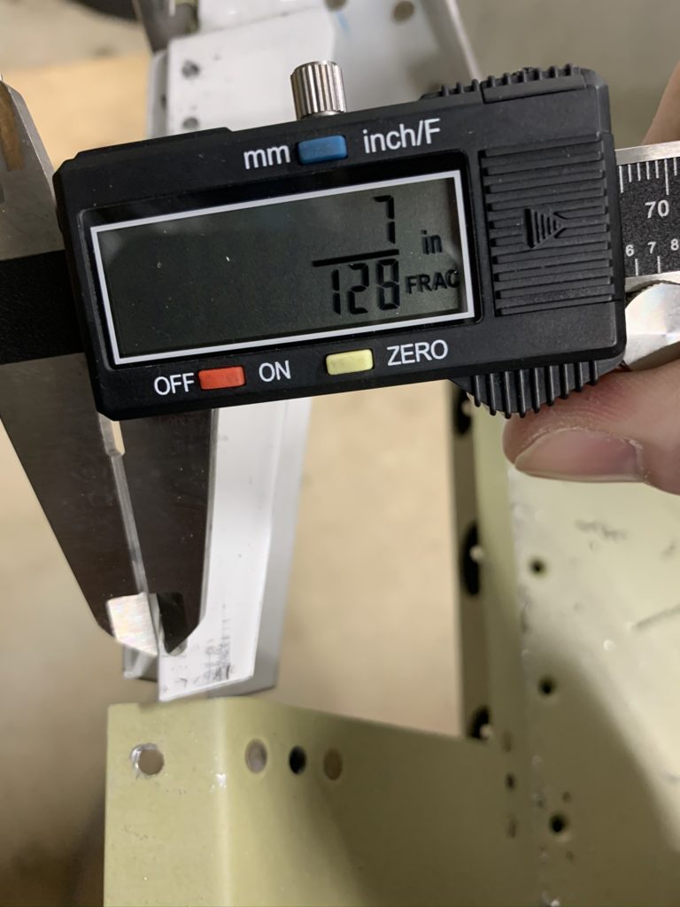
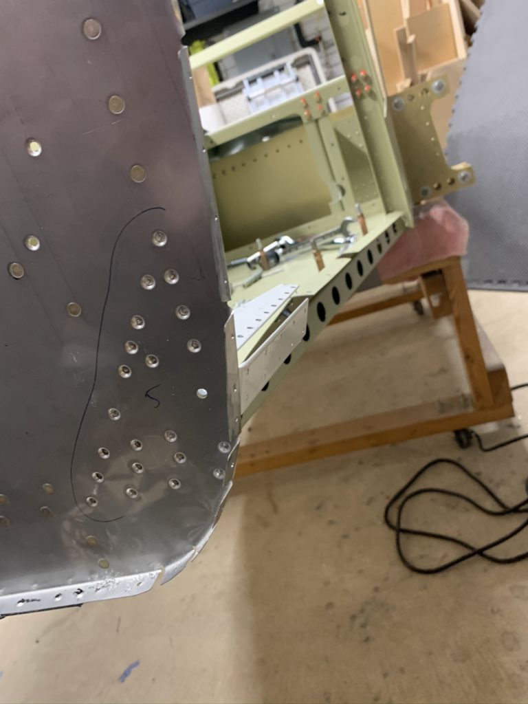
Took a few photos and sent to Vans. The first three brackets were fine, but the first photo above was concerning. Vans recommended replacement. Honestly I thought I needed to replace all my brackets, but for steel parts I really only need 1D edge distance. Ordered a new lower bracket, riveted it on, and it didn’t look right. I reinstalled the lower channel and skin to show just how off it really was. No way to pull that into alignment without putting a significant twist on the firewall. Another e-mail to Vans and they confirmed that these brackets have been problematic and they sent me a free replacement. Finally got it the day before Thanksgiving and had it installed over the weekend. Photos above of just how well the last bracket worked. Very glad I took the time (and delays) to get this done correctly!
Between all the issues with the brackets, I deburred, primed, and dimpled the skins as well as counter sunk all the understructure as called out in the plans. I did come to realize that Vans also didn’t do me any favors a few chapters back. I specifically remember not dimpling the F-1015A-L and F-1015A-R ribs after reading that chapter a few times. I even took the advice of Jason Ellis in one of his videos that these didn’t need to be dimpled because this is where the wing was. WRONG. Do yourself a favor and dimple the F-1015A ribs (and the F-1015B Intercoastals where they overlap the F-1015A ribs). If not you will find yourself digging into your bag of tricks to dimple this stuff. 🙁 I got it done but it wasn’t pretty. It’s obvious when you look at the rivets you need to install on page 29-17 Figure 1. Oh well. Another learning experience.
With that I’ll wrap up this LONG update as I’m caught up with my videos and progress to date. I’m basically ready to rivet the skins to the frame. Exciting times!
Ok, so it’s time to begin the infamous Section 29 – Side Skins. Going into this I’m already worried as there are a few new skills that I’m going to have to learn with little room for error. Bending the Longerons (yes, I did do a little of this on the Tailcone), and bending the fuselage skins themselves. No reason to drag my feet, let’s get past this and move on!
So the very first step is to bend the longerons. With memories of bending the longerons on the empennage, I decided to purchase a set of bending dies from Buller Enterprises. While not cheap, I figured they were worth a shot and I may be able to sell them at a small discount or donate to our EAA chapter tool crib. I’ll say that I’m happy with the bending dies. They worked as expected and made very quick work with bending the longerons once I got the hang of things.
With the mid-fuse longerons bent, I was about to drill the holes per the template, only to realize I bent both longerons the same way. UGH!! Remember I mentioned that I was happy I purchased spare angle aluminum? This is why! After checking I had enough spare, I went ahead and cut another longeron and correctly bent it the correct direction. Then, it was on to drilling the holes per the template.
With the mid-fuse longerons done, I moved to the fwd fuse longerons. I stressed myself out more on these as I really only had 1 shot to get these right (without costing a lot more to get a replacement shipped to me). Luckily I had sufficient practice and these went without a hitch. (I did remember that the Right and Left longerons were very different lengths!) I then also driled the holes per the templates in both of these longerons and proceeded to twist the ends of the longerons per the plans.
Then it was onto another new skill. Bending the side skins. Once again I was lucky that Todd Stoval had provided me his bending jig for my use. One less thing for me to create and I can pass it along to another builder in our chapter once I’m done with it. First thing I had to do we get more c-clamps from harbor freight. With those purchased, I then began to bend the skins ever so slightly. Honestly I was a weenie at first. After double checking other builder logs I realized I really needed to put my weight behind the bends. That really made things move along nicely. By the fourth skins, I felt more like a pro and was able to quickly bent things into position.
With the longerons and the skins ready I then assemble and drill the seat back brace and the baggage door seal angles. Pretty straight forward all things considered. Cutting down the door seals was interesting, but easily accomplished. I actually like some of the fabrication side of the build.
As I go to start installing these parts on the fuselage, I found myself getting really excited as this really starts to look nice. Then it’s on to match drilling. One thing that had me doubting myself was the drill lines on the longerons. I drew the lines at 5/16 per 29-2 Figure 1 on all the longerons and that worked well.
I borrowed an angle drill from Jeff Karrels to drill some of the holes in the longerons due to the tight spacing. After a day with this drill I decided I really needed to get one of my own. The only issue I found was with the right mid-fuse longeron where it connects to the F-1050c brace. My first attempt left the edge distance a little off for me. After checking my aluminum stock, I realized I had enough to remake yet another longeron. 10 mins later, I re-drilled and was much happier with the result. Only issue was I was a little to far off in the other direction. Decided that a thin shim would correct the situation and prevent distortion on the skin.
Lastly before I wrap up this update, I put the appropriate twist in the Fuse Channels. Only recommendation here is sand/round the corners of the wooden spaces you use.