Baggage Area – Part 2

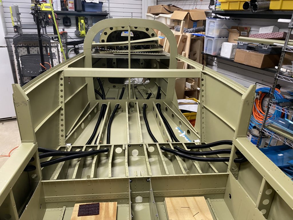
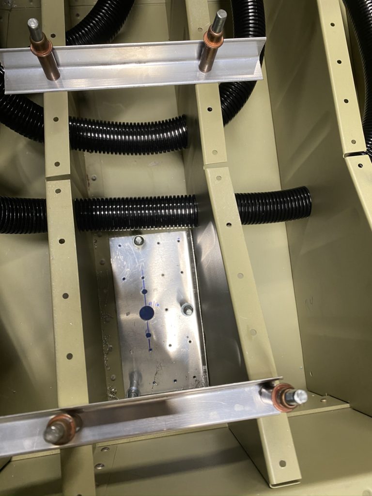
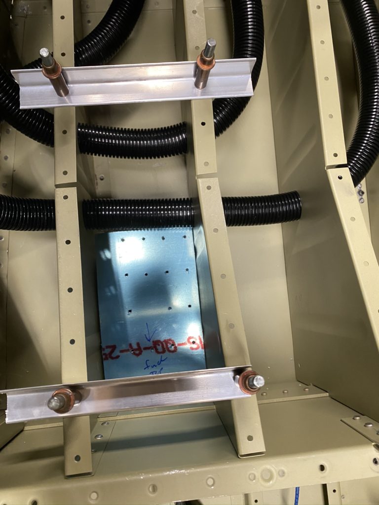
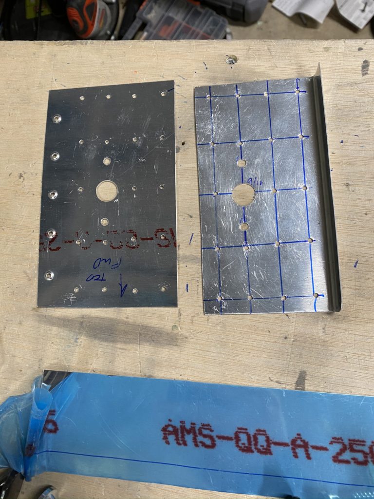
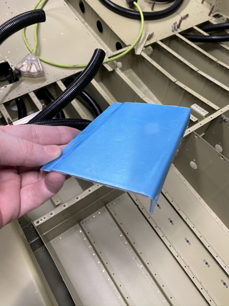
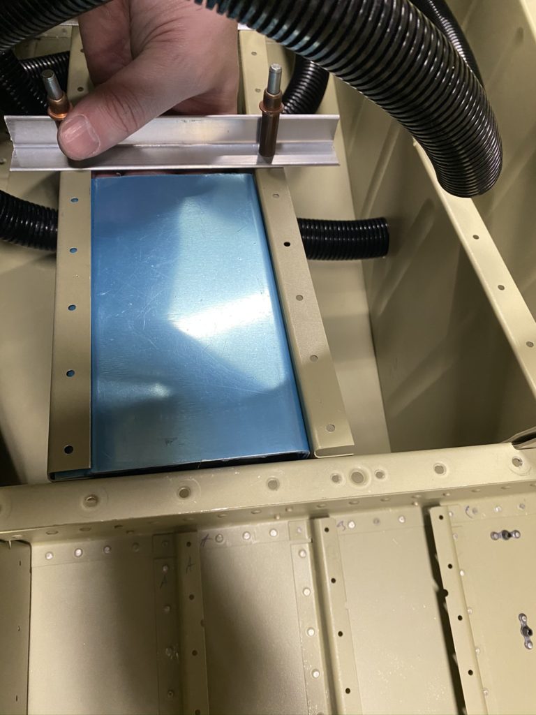
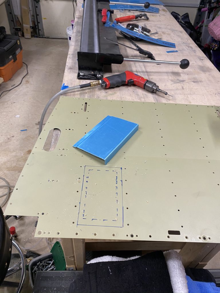
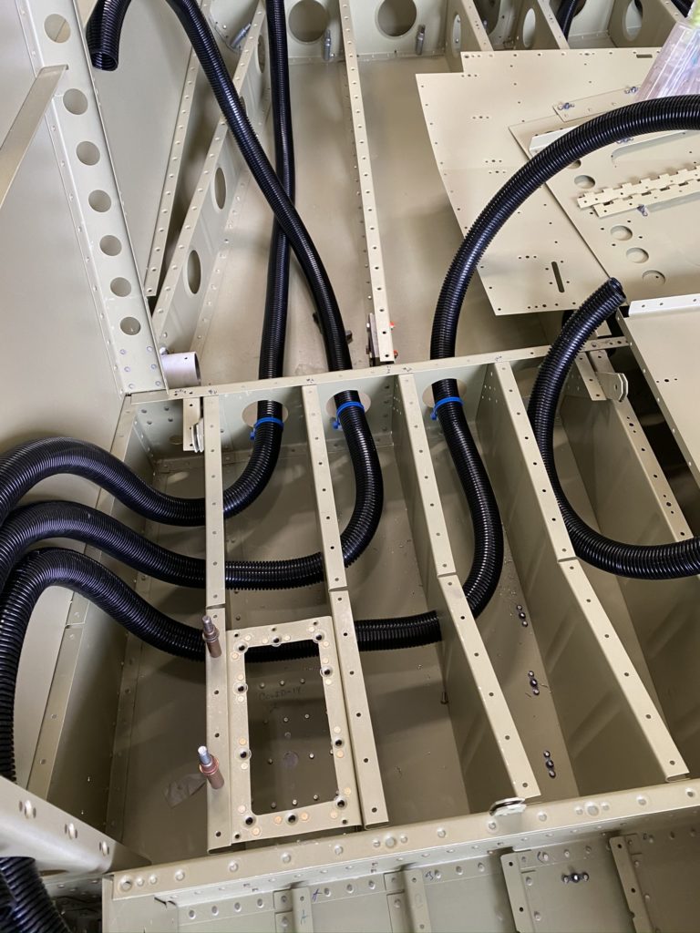
With the conduit run under the rear seat I’m just about ready to install the baggage floor. Looking at the conduit running under the baggage area, it’s obvious it needs to be supported. I don’t have a lot of clever ideas so I end up doing something simple. I use some scrap aluminum and create a support bar that I can zip-tie the conduits to. This is basically a “Z” piece that supports the conduit and keeps things from bouncing around.

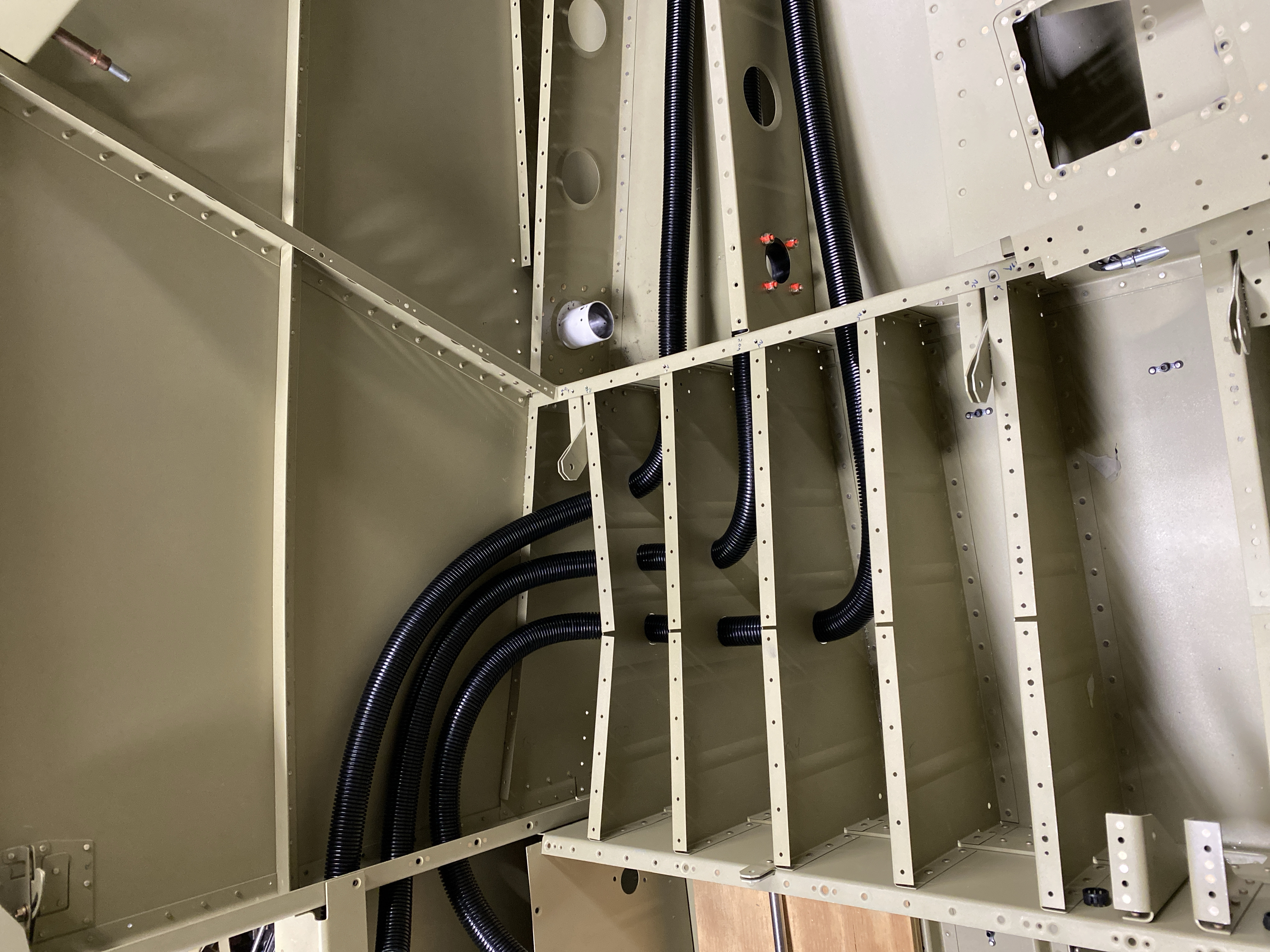
I didn’t mention in the last update that I also installed lightening hole mounts for the conduits under the seats and under the door sill so the conduit is supported at the bulkhead behind the rear seat (just in front of the step), the “Z” bracket, and then another lightening hole support at the baggage bulkhead.

On the left side of the baggage area, I ended up making a slightly better support mount out of angle aluminum and one of the standoffs. I’ll just have to add a step to inspect these using my borescope at my condintion inspections to make sure things supported correctly. If necessary I’ll swap it out but don’t expect any issues.

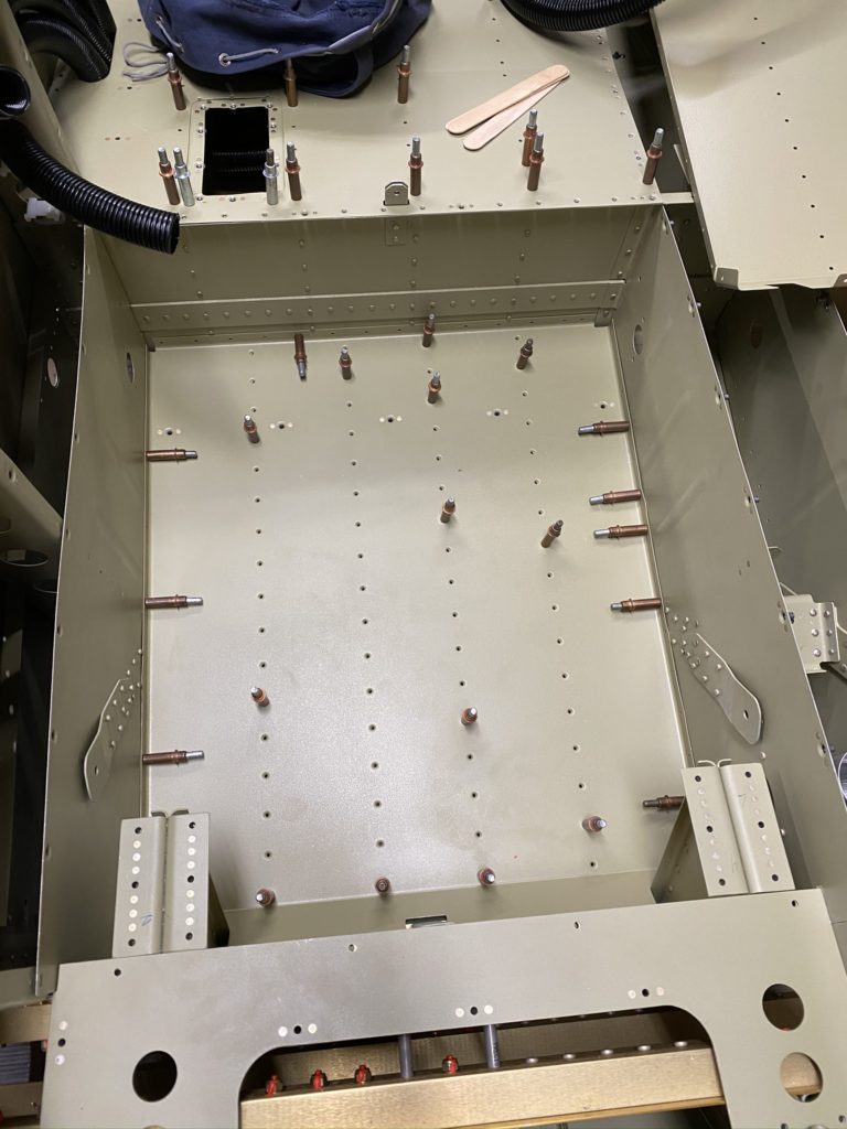
With the conduits installed and supported, it’s time to install the baggage floors and rear seat pans. Besides pulling the conduit through the holes in the rear seat floors, this was not difficult at all. I install the hinge half for the rear seat backs, and rivet the rear seat to the aft bulkhead. I also rivet down the baggage floors with CS rivets per the plans.

At this point I could rivet the rear seats, but as the plans tell you not to, I’m waiting. I think this is to make sure you can access to install antennas or run wires, but I think I have that figured out at this point. Regardless, I’m holding off for a bit just in case something surprises me.

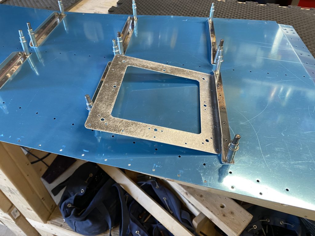
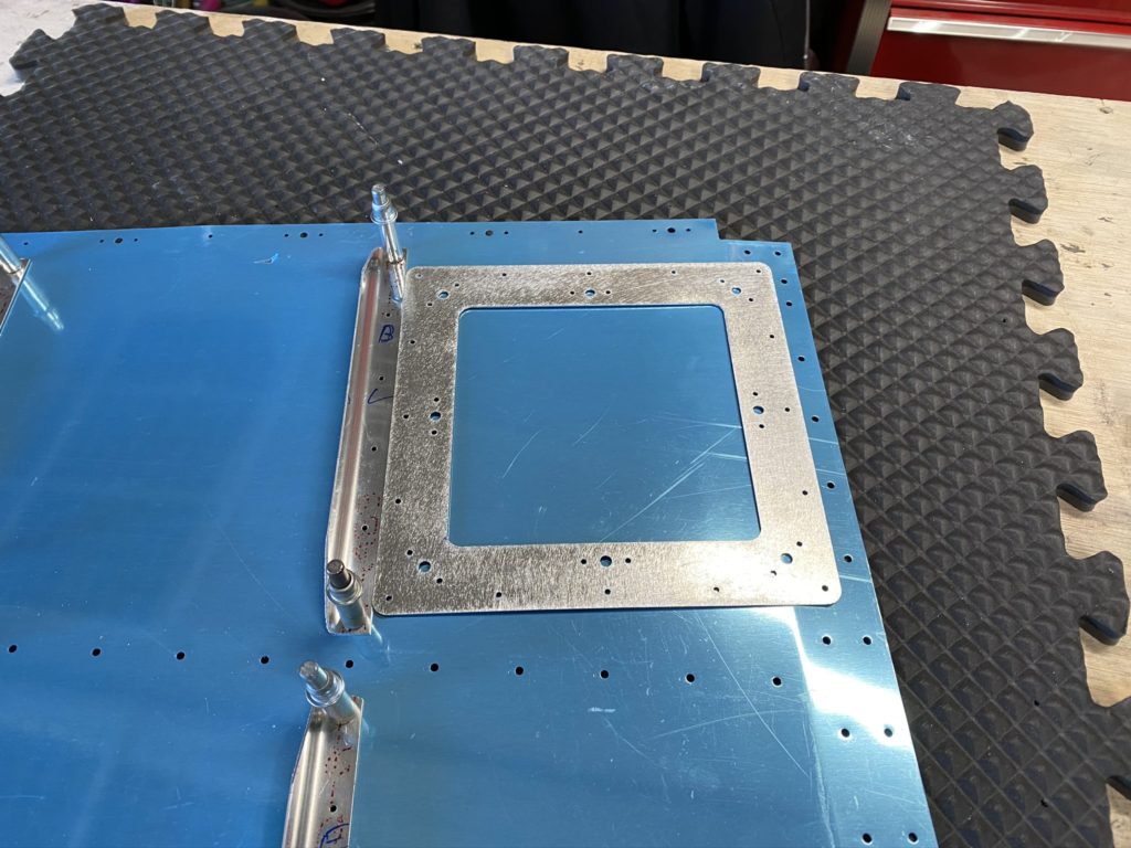
Next step was installing the side panels for the right side of the baggage compartment. I trimmed off the nub and set the panel in place. Next was installing the baggage bulkheads and match drilling the holes. I misread the directions and didn’t have my side panel clecoed properly in place, so that one hole that matches with the bulkhead needed to be “adjusted”. Luckily there is a nutplate installed behind it, so I should be fine.

Drill all the holes in the bulkhead to structure underneath, then use the nutplate jig to drill the nutplate attach holes. At this point it’s pretty routine. Get everything drilled, deburred, and painted. I didn’t install the seatbelt harness stuff yet, as I have to figure out some modifications to the rear baggage bulkhead for the airconditioner hookup.

This basically completes this section but I put a reminder to revisit a few items as I get closer to the end of the build.

Access Covers and Floor Panels – Part 1

About halfway through working on the baggage floors and rear seats, I realized that I probably should install the rear floor pans before I even put the rear seat panels on. Of course I realized this AFTER I created and installed my rear seat access panel and had the conduit run through the left seat floor cover.

After looking at my fuselage and the plans, I realized I made a minor mistake earlier in the build. For whatever reason, when I installed the rivets on the tunnel for the front seat brackets, I installed them with the shop heads in the rear foot well. This isn’t a huge deal, but it did make life a little more difficult to install the rear floor. Between that and the concern I would bend something trying to remove the floor pans, I elected to only install the floor pan once.

Instead of match drilling, I just reamed all of the holes on the floor pan, deburred and then primed both floors. I did slightly test fit the floor when it matches against the forward seat supports and needed to file a few places so everything with fit perfectly. I then reamed all of the matching holes on the stiffeners. Once done, I dimpled the floor and installed the nutplates. On the ribs already installed in the fuselage, I had to use my vice grip dimple set on all the holes. Not sure how else you can do this as none of my yokes would come close to fitting in that tight space.

To install the floors, I really had to push the tunnel panels with some force to get the floor past the shop head of the rivets. Then, with a little push on the aft end of the floors, it dropped into it’s final location and fit perfectly. I think I made the correct choice as getting it out once it’s in looked like it would be a royal pain.

With the floor in place, I clecoed to get the ribs to line up, then began to install all the countersunk blind rivets to attach the floor to the ribs. With the CS blind rivets in, I then drill the fwd holes into the spar web, give a light deburr and install the LP4-4 rivets.

With the blind rivets all installed, it’s on to installing the AN470 rivets to the tunnel, fuse side, and rear seat spar. This is where not having the seat pan installed would make life a little easier. Installing the rivets in the tunnel and rear seats isn’t too bad. Getting to the side walls was a little more tricky. Also the plans don’t call out you need different size rivets for the places where the seat belt tie-down are in the tunnel. I also noticed one location on the rear seat is REALLY close to one of the ribs and almost impossible to set correctly. Not sure if I installed a rib backwards or something, or if it’s just a funky location. I got it set, but it’s not pretty.

Need to finish up the baggage area before I go further with the access covers. I already know I need to make modifications to the tunnel cover for the Control Approach pedals and the center console fuel selector.

Comm antenna, Rear Seat Access Panel, and Conduit

As I worked on the floors to the Baggage area and Rear seat, I realized that I need to run conduit as well as identify where to mount my comm antenna. Reading lots of posts on VAF, I had some initial thoughts on what to do for conduit, but hadn’t thought too much about the comm antenna yet.

I wanted a belly mounted comm antenna, however I was worried that my air conditioner scoop would be a problem / cause interference. I did notice that some other builders had also installed a bent whip antenna under the rear seat with the airflow scoop installed so I’m feeling that this shouldn’t be an issue.

First things first, I need to lay out where I’m going to run my conduit so I can pull wires from the instrument panel to the rear of the airplane. I’m in the camp that you can’t have too many conduits, so I wanted to run six 1″ conduits from just in front of the rear seats to the baggage bulkhead.

With the conduits laid out, I drilled holes through the seat ribs, and pulled the conduit into final position. Let’s just say that pulling the conduit through the holes is not something I want to do again. I would highly recommend hearing protection and gloves.

With the conduit run, I then shifted my focus to the comm antenna. Previously I had purchased a DeltaPop bent whip antenna after hearing they performed well and were on the inexpensive side. With the antenna in hand, and the location of where to install identified (Second bay of the rear seat from the outboard side), I needed to figure out how to install it. The only issue with the Delta Pop antenna over a Comant is that you have to have access to the interior side where you mount it. It only has two studs that you have to install nuts on vs the Comant where you can install nutplates on the interior and remove the whole antenna from the outside of the aircraft. Minor detail that means that I need to create an access panel on my rear seat pan.

Before I do that, first things first. I need to create a doubler for the antenna. Actually I need to create a shim, then a doubler for the antenna to ensure everything was connected together appropriately. For the shim, I used a piece of .024 aluminum, and bent one edge up to tie it into one of the ribs and wide enough sit flat against the other rib flange. Then I created a doubler of .032 that would cover the shim and the rib flange.

With the Shim and Doubler cut to size, I then lay out the rivet pattern. I’m just sharing what I did, but if you want to do it “correctly” then get AC 42.13-b and have a read. I drilled the following pattern in my “shim” which should be sufficient (see photo above). I then placed the shim in the fuselage to match drill the holes into the skin. Next was to use the shim to drill the hole pattern into the doubler. The last holes to drill were the dimpled holes in the rib flange. I ended up clecoing the doubler to the outside of the skin and using my hole finder to drill these holes. I then test-fit the antenna and all looks good!

With the antenna sorted, it’s time to figure out the access panel. Honestly, there is no good/easy way to do this that’s obvious to me, so I’m improvising. The distance between the ribs is pretty tight. Adding a flange for an access panel just makes it more difficult for my meat paws. I may end up having my kids or wife help if I need to get in here in the future.

I fabricated a doubler / flange as best I could. Just like the shim, it will rivet to one rib, but I made a joggle so I can blind rivet it to the rib flange when I install the seat pan. It’s not perfect, but it should work.

With the rough access panel created, I go ahead and layout and cut out the hole in the seat panel. Lots of careful measurements followed by some filing and trying to keep things looking straight. This is not a CNC cut perfectly created access panel, and honestly it will be covered by a seat so nobody will see this except me. For what I needed, this will work.

I then get my wife to assist me in riveting the shim and doubler onto the bottom skin. I temporarily install the antenna (after some minor filing) and am quite happy with how it looks. Put the antenna into storage, and then pull the conduit through the seat bottom so I can continuing working on the Baggage Area. Once the access panel ring is blind-riveted in place, I’ll have to use my squeezer to set the last few rivets.

Baggage Area – Part 1

Section 33 has you closing up the baggage area floors and the rear seats as well as some of the side panels. Previously I had cut the baggage area ribs and matched drilled them to the baggage floors. I had purchased a set of Baggage area access panels from AirWard, however they would not work without serious modifications. Luckily I was able to return them to AirWard and just purchased the Vans Access panel VA-195D and VA-195C which worked perfectly.

I went ahead a primed everything, and got all the parts dimpled per the plans. I spent a little extra time making sure I didn’t dimple the wrong holes as the left and right floors do have some differences due to the baggage door.

I then back rivet all the floor ribs and access panel ring and cleco everything together. After taking a moment to appreciate how it all looks, I then have to start to think about running conduit before I begin to rivet the floor down. I’m making this a short update as I will discuss the conduit runs and other modifications in a follow-up post.

Air Conditioner Scoop

With the next few steps in the plans having me rivet down the rear floor and seat panels, I realized that now was the time to install the Air Conditioner scoop. The kit for the AirFlow systems includes riv-nuts, however I have heard enough complaints regarding riv-nuts that I decided that since I have access I’m going to just install nutplates.

The first step is to mark the center line of the air scoop as well as the center line of the aircraft as you really want this to be perfectly centered. I spend a lot of time making a lot of measurements to try to make sure I get this correct. I’ll just say that the reflections from the skin and how I have my project sitting in my garage really did make this a difficult task as what I was seeing vs what my measurements were telling me did not agree.

I used making tape on the fuselage, a cardboard template I created from the scoop itself, as well as installing masking tape from down the length of the scoop to help me mark the centerline. I finally got to the point where I had to make the first hole in the skin. With the scoop clecoed to the skin, I drilled all screw holes and avoided drilling any of the spars.

Only after I did this did I read that someone used a sheet of acrylic to template the scoop so they could see where they were drilling. That was very smart and I wish I thought of it. Something to remember in the future I guess.

With all of the holes drilled, I used my nutplate jig to drill all the #40 holes for the nutplates. I then had to enlist my daughters to help me dimple the holes using the close quaters dimple tool. This is the dimple set that has a hole in the center and copper rods and nails to set the dimple.

Pro-tip: I found that the Stainless Finishing nails from Home depot were perfect vs the nails included in the tool. I ended up ruining a set when I pulled a nail though the dimple dies and had to get a replacement set.

With all the holes dimpled, I had my wife assist with back riveting the nutplates. After installing the scoop to make sure everything looked good, I needed to drill the holes for the radiator (condenser) into the center tunnel. This made a template and drilled the holes into the center tunnel. The instructions don’t tell you that you need to put a doubler around these holes, but I’m thinking that installing one may be a good idea. It’s on my list of things to do “later”

With the scoop installed, I putting the AC stuff off to the side until I get the baggage bulkhead installed At least I can store the scoop on the bottom of the plane for now so it’s out of my way.