As I worked on the floors to the Baggage area and Rear seat, I realized that I need to run conduit as well as identify where to mount my comm antenna. Reading lots of posts on VAF, I had some initial thoughts on what to do for conduit, but hadn’t thought too much about the comm antenna yet.
I wanted a belly mounted comm antenna, however I was worried that my air conditioner scoop would be a problem / cause interference. I did notice that some other builders had also installed a bent whip antenna under the rear seat with the airflow scoop installed so I’m feeling that this shouldn’t be an issue.
First things first, I need to lay out where I’m going to run my conduit so I can pull wires from the instrument panel to the rear of the airplane. I’m in the camp that you can’t have too many conduits, so I wanted to run six 1″ conduits from just in front of the rear seats to the baggage bulkhead.
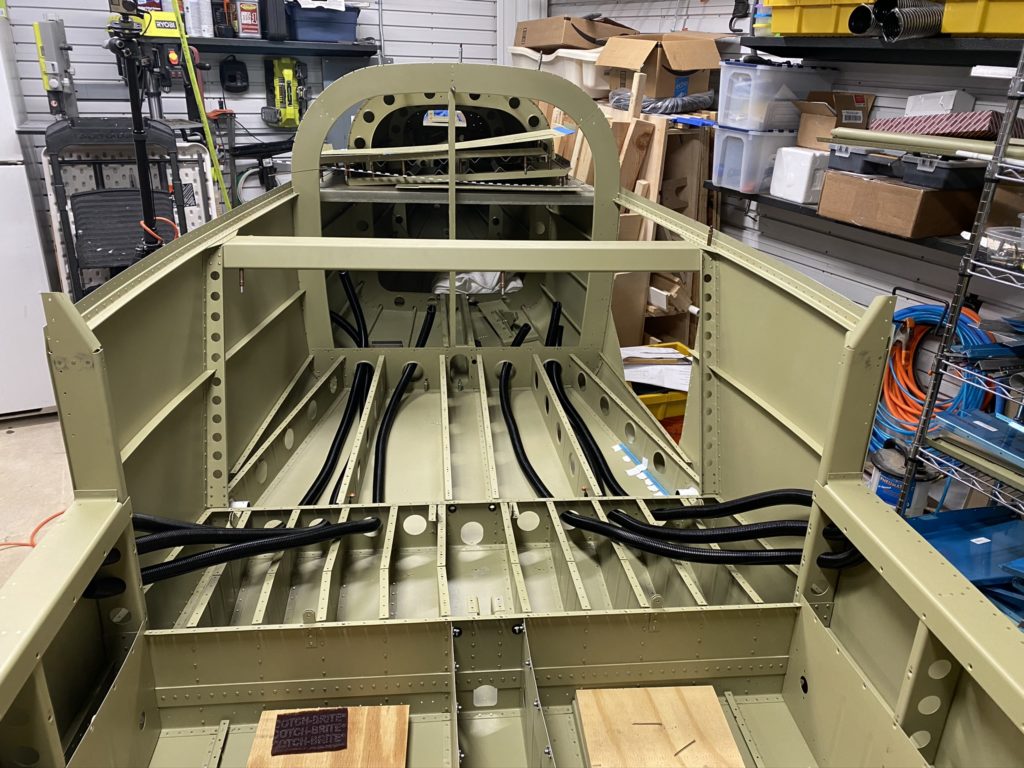
Rough Layout 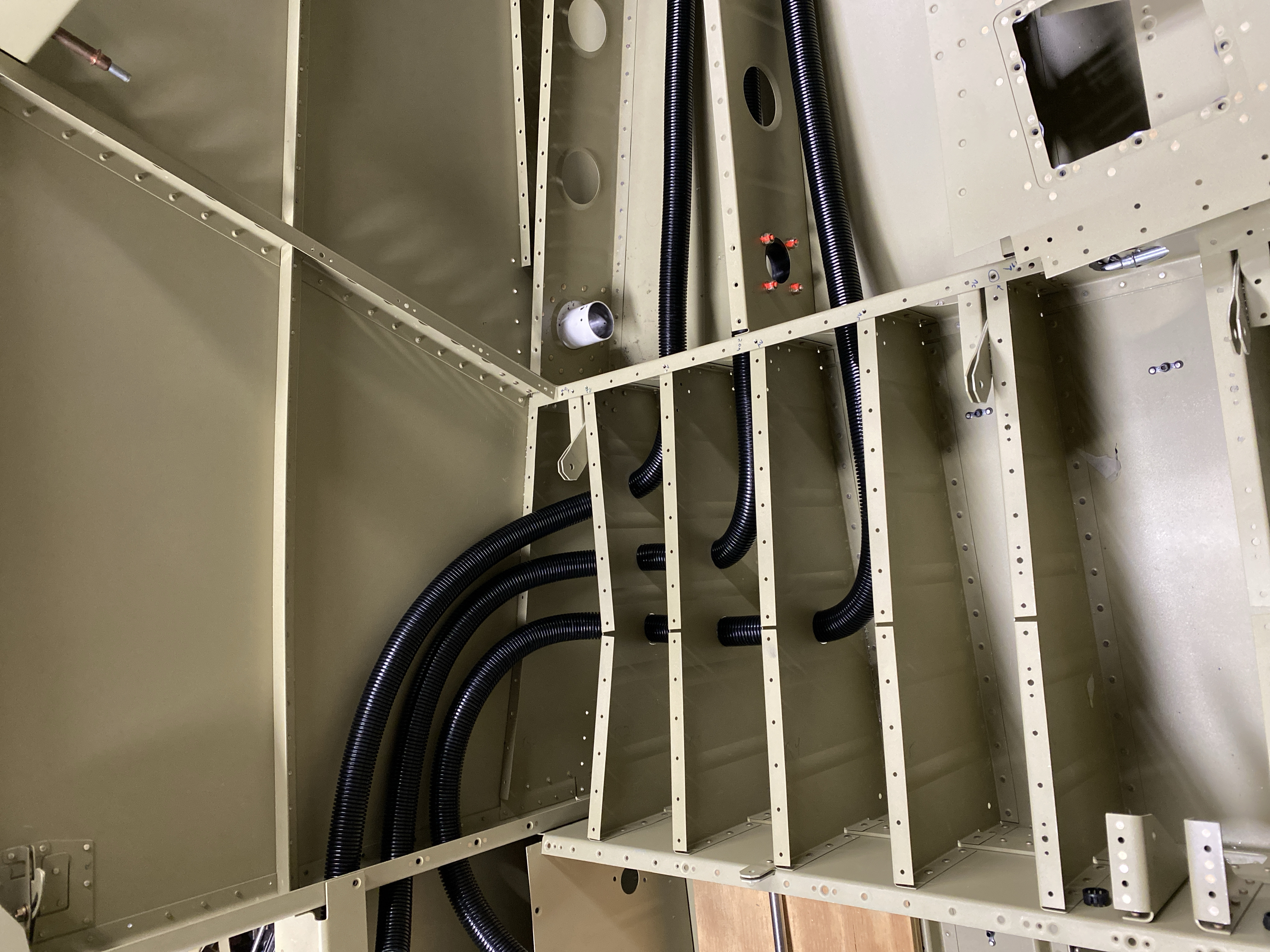
Pulled through ribs
With the conduits laid out, I drilled holes through the seat ribs, and pulled the conduit into final position. Let’s just say that pulling the conduit through the holes is not something I want to do again. I would highly recommend hearing protection and gloves.
With the conduit run, I then shifted my focus to the comm antenna. Previously I had purchased a DeltaPop bent whip antenna after hearing they performed well and were on the inexpensive side. With the antenna in hand, and the location of where to install identified (Second bay of the rear seat from the outboard side), I needed to figure out how to install it. The only issue with the Delta Pop antenna over a Comant is that you have to have access to the interior side where you mount it. It only has two studs that you have to install nuts on vs the Comant where you can install nutplates on the interior and remove the whole antenna from the outside of the aircraft. Minor detail that means that I need to create an access panel on my rear seat pan.
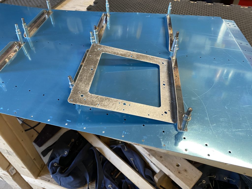
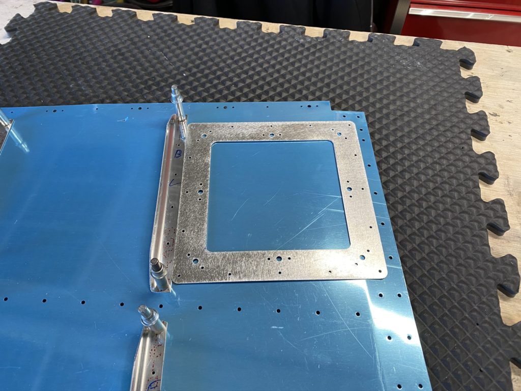
Before I do that, first things first. I need to create a doubler for the antenna. Actually I need to create a shim, then a doubler for the antenna to ensure everything was connected together appropriately. For the shim, I used a piece of .024 aluminum, and bent one edge up to tie it into one of the ribs and wide enough sit flat against the other rib flange. Then I created a doubler of .032 that would cover the shim and the rib flange.
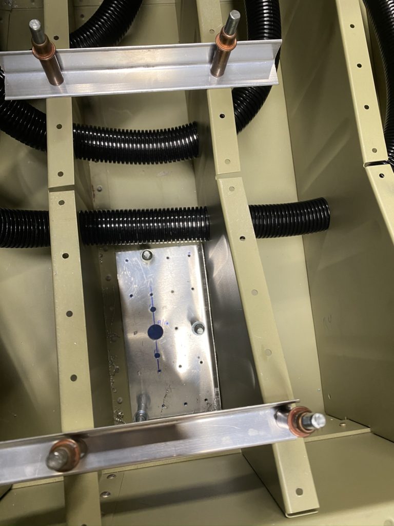
Shim 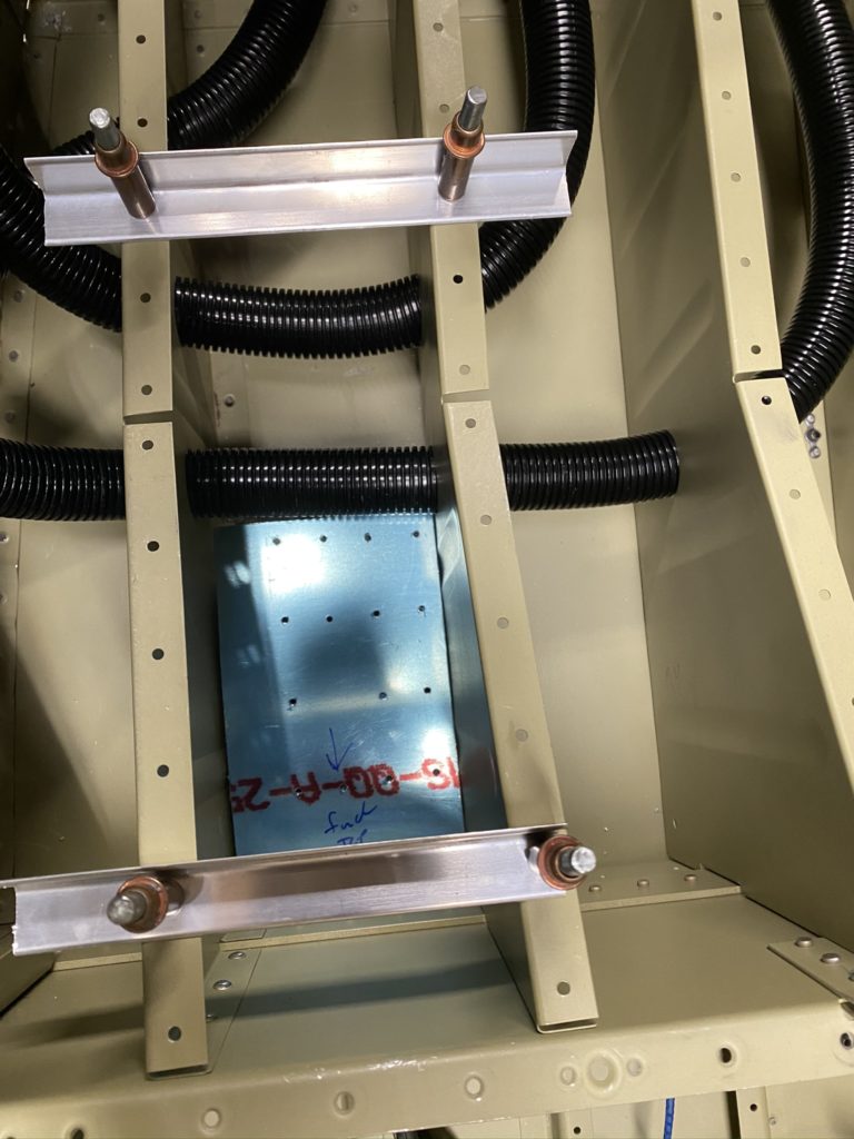
Doubler 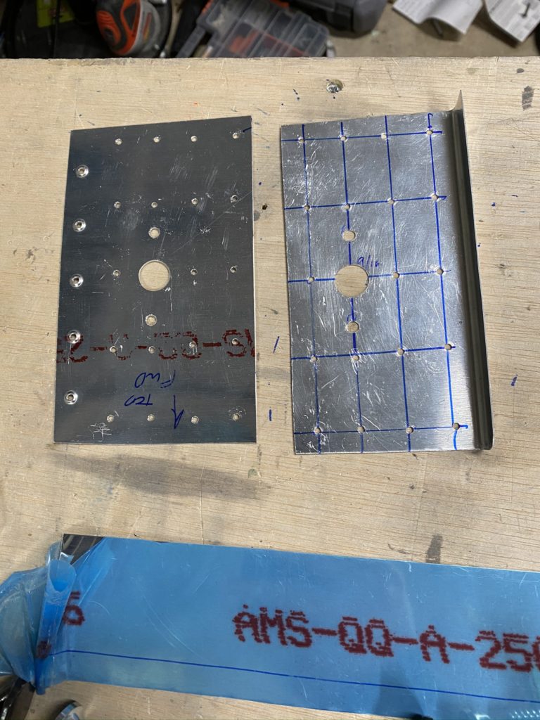
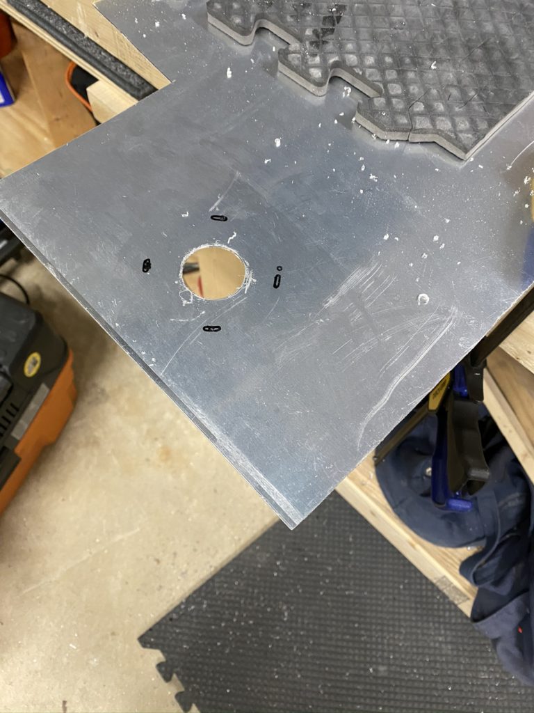
Rivet pattern
With the Shim and Doubler cut to size, I then lay out the rivet pattern. I’m just sharing what I did, but if you want to do it “correctly” then get AC 42.13-b and have a read. I drilled the following pattern in my “shim” which should be sufficient (see photo above). I then placed the shim in the fuselage to match drill the holes into the skin. Next was to use the shim to drill the hole pattern into the doubler. The last holes to drill were the dimpled holes in the rib flange. I ended up clecoing the doubler to the outside of the skin and using my hole finder to drill these holes. I then test-fit the antenna and all looks good!
With the antenna sorted, it’s time to figure out the access panel. Honestly, there is no good/easy way to do this that’s obvious to me, so I’m improvising. The distance between the ribs is pretty tight. Adding a flange for an access panel just makes it more difficult for my meat paws. I may end up having my kids or wife help if I need to get in here in the future.
I fabricated a doubler / flange as best I could. Just like the shim, it will rivet to one rib, but I made a joggle so I can blind rivet it to the rib flange when I install the seat pan. It’s not perfect, but it should work.
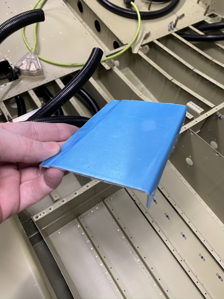
Access ring bent using the duckbill pliers 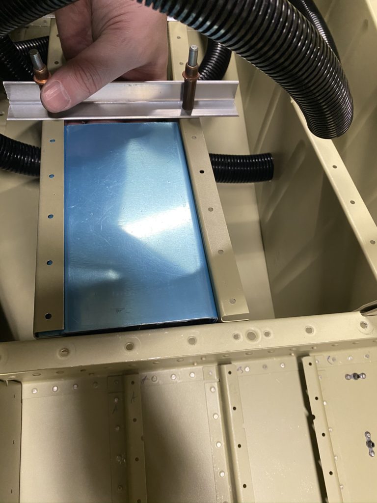
Looks like it should fit 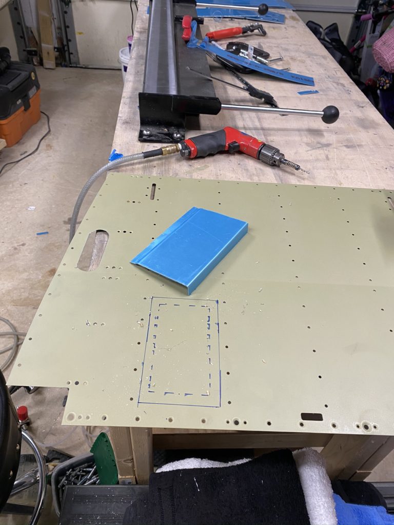
Mocking up where to cut 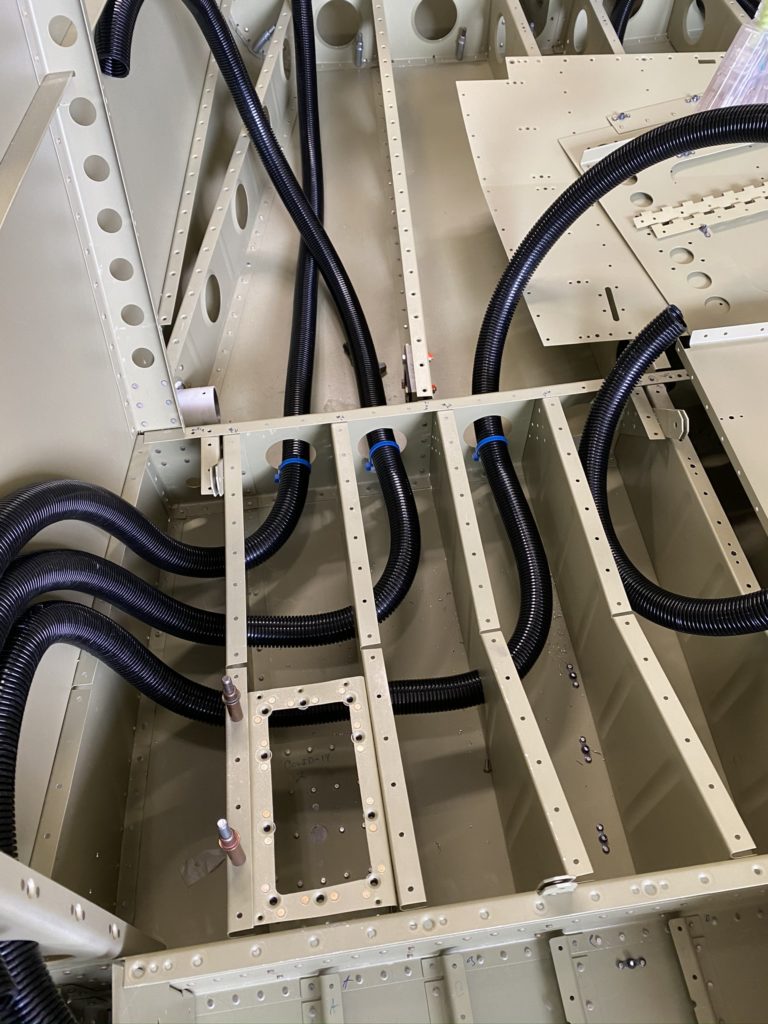
Still looks good.
With the rough access panel created, I go ahead and layout and cut out the hole in the seat panel. Lots of careful measurements followed by some filing and trying to keep things looking straight. This is not a CNC cut perfectly created access panel, and honestly it will be covered by a seat so nobody will see this except me. For what I needed, this will work.
I then get my wife to assist me in riveting the shim and doubler onto the bottom skin. I temporarily install the antenna (after some minor filing) and am quite happy with how it looks. Put the antenna into storage, and then pull the conduit through the seat bottom so I can continuing working on the Baggage Area. Once the access panel ring is blind-riveted in place, I’ll have to use my squeezer to set the last few rivets.