Cabin Top – Part 2

With the cabin top basically fitted, I finally gathered my courage and started to drill the aft end of the cabin to the top skin. I had a small mental block as this seemed like permanent step and I really wanted everything to line up perfectly. Finally got to the point where I had to get over myself.

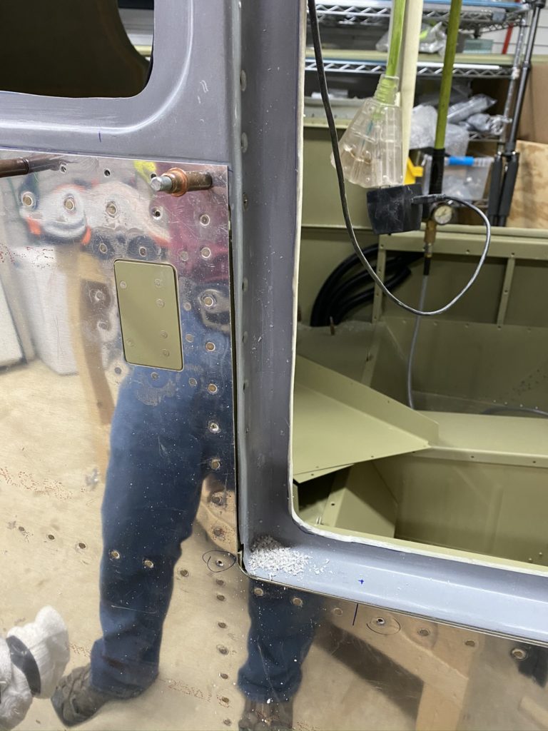
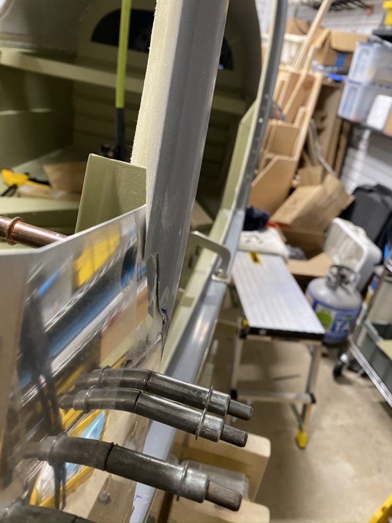
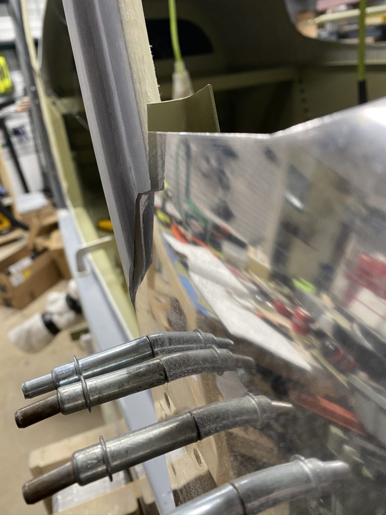
Some small notes: the mid fuse skins did not fully touch the top of the joggle on the cabin top. This was not due to hitting the longerons but due to the door sills needing to be sanded more I guess. I basically had the door sills sanded flush, so I made the decision that it was good enough and I would fair it out with epoxy/flox/micro. We are talking about maybe a 1/16″ gap.

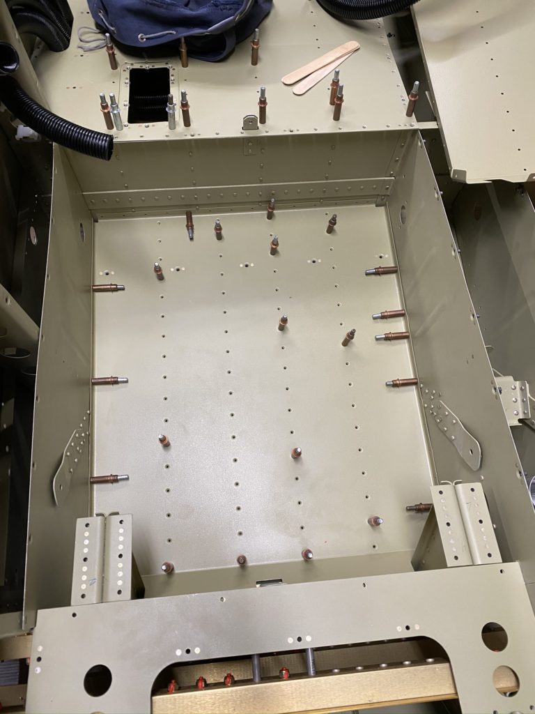
I use some scrap 2×4’s and a reversible clamp and apply some upward pressure on the cabin top so it is tight against the top skin. I then start at the center of the cabin top, and match drill #40 all the holes between the three top longerons. I clean out any trapped dust, then go back to the center and up-drill the holes to #30. This reduced the dust that got between the cabin top and the skin as I drilled at the expense of taking a little longer. Maybe a wash on time/effort.

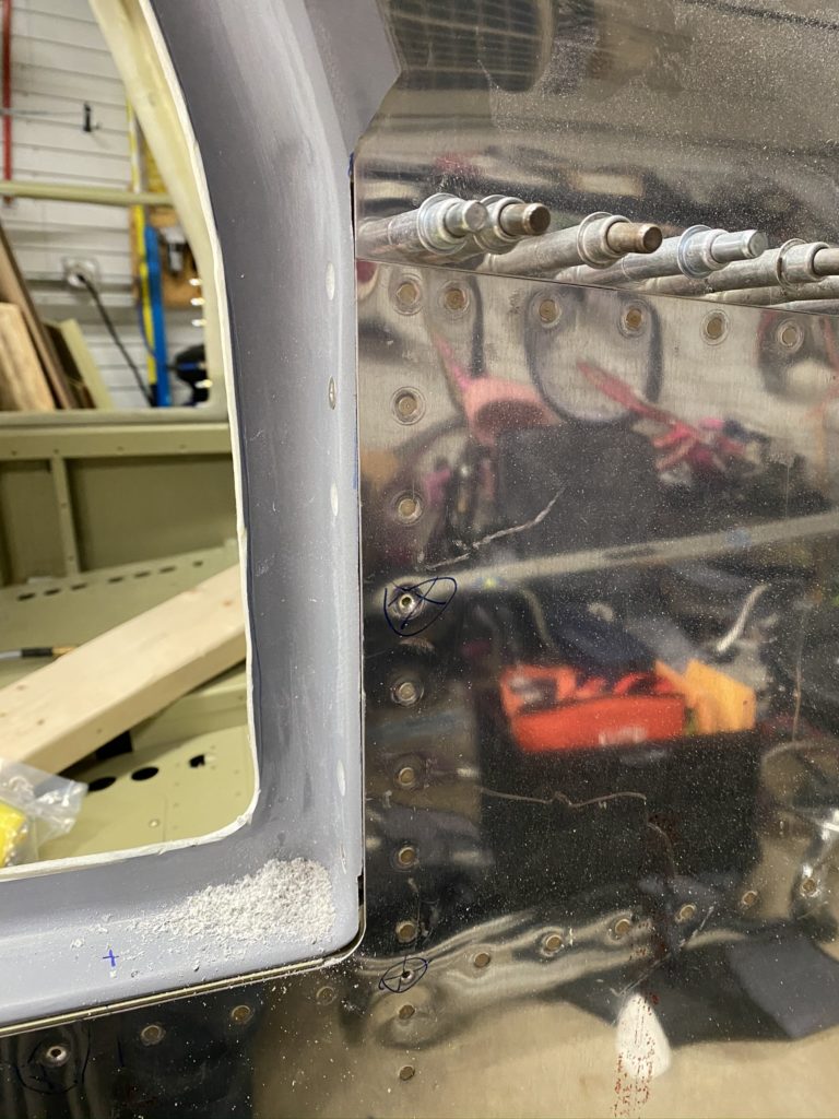
With the top holes drilled I reposition the wood and clamps so I am appying pressure to the sides of the cabin top and I repeat the same process along the rest of the aft end of the cabin top. Things got progressively easier as I went along and only had to stop a few times to clear out dust between the parts. I then shift my wood shims and drill every 8th hole down the side of the mid-fuse skin into the cabin. Same process. Drill #40, then updrill to #30.

Next was drilling the screw holes into the door sides. I lined up the cabin top per the plans and clamped into place. Using a 90 degree drill, I make the initial #30 hole clecoing as I go. Then up-drill using my regular drill to #12 and using my 3/16 clecos to keep everything in place. To countersink the holes, I end up using my 90 degree drill with the countersink bit in it as I didn’t have a threaded to chucking adapter. I had to free-hand countersink the holes to fit the screws and installed 2-3 screws on each side to keep things in line.

Next I transfer the markings from earlier in the chapter to the cabin door sill and drill the holes up to #19. With a few screws installed the door is pretty solid so I then begin to install the front cabin brace. I then measured and marked the centerline of the cabin top to help align the cabin brace.

Cabin Top – Part 1

With most of the interior completed, I was eager to finally get the Cabin top. Honestly pulling the cabin top down has been one of my “goals” for a while. I was originally hoping to have the cabin top started in December of 2019, but hey, stuff happens.

With the assistance of my wife, we get the cabin top off the ceiling and on to my work bench. I inspect the scribe lines and find the a number of them are a bit off compared to the plans. Using my calipers, I re-scribe lines and mark them with my sharpie. Then it’s time to start trimming.

Ok, so this part kinda sucks. I tried a few different tools with different levels of success. First was the oscillating multi-tool that was recommended in the fiberglass class. This is pretty light on dust, but it’s loud, hard on your hands and cuts SO SLOW!. Also the tool was a bit heavy and I got tired before I finished my first cut line. I then decided to switch to the Dremel tool with a cutoff wheel. I moved the cabin outside and started it up and it cut pretty good. It did EAT a lot of those tiny disks and my lines were really that straight, but it worked. I had enough disks to at least cut the door sill, under the rear windows and the aft end of the cabin top.

With these done, I enlisted the help of my wife and two girls. Let’s just say that my girls were more excited to help than I expected. They absolutely loved to climb into the cabin and crawl around to help out. With their help holding the weight on the rear of the cabin top, my wife and I tried to slide the door frames between the cabin pillars.

I REALLY didn’t want to sand too much off, so we did this 5-6 times with me sanding a little each time before we could get the cabin top to bottom out. Then I had to mark where I had interference, both in the door frames and under the rear windows where the cabin top hit the longerons. To sand things down at this point I used a Ryobi belt sander from Home Deopt with some 40 grit sand paper. The belt sander could chew through the fiberglass with a little pressure, or just lightly sand if needed.

On and off another 4-5 times as I sand a little here, a little there, I finally felt like I had things almost perfect. The frame is thin in a few places, but looking at posts from others, this really isn’t unusual. I can build it up with some epoxy and flox without too much issue.

Added a few photos to show examples of how close a fit I got. This was hard to visualize so I ended up sanding a little too much in a few places. Not the end of the world. Overall really happy with how it turned out so far. I will say that making the cuts, and then eventually drilling the holes in the canopy top is scary the first time you do it! All went well – no regrets.

Baggage Door

I had actually started to assemble the Baggage Door itself a while ago when I was waiting to get my wife to assist with some riveting. The door itself is pretty straightforward. Bending the pre-cut channel and cleco to the outer door skin. then cleco on the lock bracket in place and add the inner skin. Match drill everything, disassemble, deburr and prime all but the outer skin.

I wanted to do the same “mod” that Ed and Colleen did on their baggage door. I cut the hinge to length, and cut the center three eyelets back just enough to get the hinge wire out. I then put the door in place on the airplane to mark where the door side hinge should sit. I found that by using a piece of gorilla tape on the fuse skin edges, I could make “shims” to better center the door and have a consistent gap. This seemed to work well for me.

Once the hinge locations were marked on the door, I did my best to eyeball how proud the eyelets should protrude from the skin. I then drilled the holes basically following the directions from VANS, and began to rivet everything together.

When I went to hold the door in the opening, I realized that I didn’t have the hinge where I wanted it. Crud. It was a little low, so I needed to drill out the inner skin that I already installed with pop rivets, and then drill out the hinge. I did that successfully, and used a strap duplicator to re-locate a new hinge piece where I wanted it. Match drilled everything again, primed the new hinge piece, and reinstalled. Looked much better.

I then went to my scrap pile and found some scrap .063 aluminum and cut some “shims” to go between the substructure and the outer door skin. I taped these to the door so the scrap was at the edge of the skin and the gorilla tape acted as a centering shim just like before. I installed the door post in the airplane and modified the clecos per the plans.

I swear you need 7 hands for the next step. Holding the door in place, putting pressure on the plane hinge so it sits flat against the door post while also lifting up so the door doesn’t drop the .035″, and holding the drill while you try to make the first hole. Somehow I did this with some measure of success. I also tied to drill the top most hole as high as possible with my right angle drill. This is great, but doesn’t allow a cleco to be installed. Drill a hole or two further down, and cleco goes in just fine. Now I can see the door swing.

Ok, so the door will not fold flat against the airplane but does open enough to get luggage in. I’m leaving it for now as it looks like it will work. I’ll have to see if this will be a problem for paint scraping (maybe some wear tape on the door edge in my future?)

I also ordered locks from the aviation department of Amazon. Got the 7/8″ version that worked great. I didn’t used the lock arm from Vans, but the one included in these locks were perfect. Only thing it didn’t have was the tabbed washer that I’ll have to order from VANS next time I place an order for something. At least I now have 4 locks (2 doors + Baggage + spare). I’ll have to make extra keys, but happy so far.

With all of this done, I just have to disassemble, deburr, prime anything that needed it and rivet everything together. I then install the doors and they look great. Only thing I still need is the weatherstripping to put around the door edge so it doesn’t rattle.

Baggage Area – Part 2

With the conduit run under the rear seat I’m just about ready to install the baggage floor. Looking at the conduit running under the baggage area, it’s obvious it needs to be supported. I don’t have a lot of clever ideas so I end up doing something simple. I use some scrap aluminum and create a support bar that I can zip-tie the conduits to. This is basically a “Z” piece that supports the conduit and keeps things from bouncing around.

I didn’t mention in the last update that I also installed lightening hole mounts for the conduits under the seats and under the door sill so the conduit is supported at the bulkhead behind the rear seat (just in front of the step), the “Z” bracket, and then another lightening hole support at the baggage bulkhead.

On the left side of the baggage area, I ended up making a slightly better support mount out of angle aluminum and one of the standoffs. I’ll just have to add a step to inspect these using my borescope at my condintion inspections to make sure things supported correctly. If necessary I’ll swap it out but don’t expect any issues.

With the conduits installed and supported, it’s time to install the baggage floors and rear seat pans. Besides pulling the conduit through the holes in the rear seat floors, this was not difficult at all. I install the hinge half for the rear seat backs, and rivet the rear seat to the aft bulkhead. I also rivet down the baggage floors with CS rivets per the plans.

At this point I could rivet the rear seats, but as the plans tell you not to, I’m waiting. I think this is to make sure you can access to install antennas or run wires, but I think I have that figured out at this point. Regardless, I’m holding off for a bit just in case something surprises me.

Next step was installing the side panels for the right side of the baggage compartment. I trimmed off the nub and set the panel in place. Next was installing the baggage bulkheads and match drilling the holes. I misread the directions and didn’t have my side panel clecoed properly in place, so that one hole that matches with the bulkhead needed to be “adjusted”. Luckily there is a nutplate installed behind it, so I should be fine.

Drill all the holes in the bulkhead to structure underneath, then use the nutplate jig to drill the nutplate attach holes. At this point it’s pretty routine. Get everything drilled, deburred, and painted. I didn’t install the seatbelt harness stuff yet, as I have to figure out some modifications to the rear baggage bulkhead for the airconditioner hookup.

This basically completes this section but I put a reminder to revisit a few items as I get closer to the end of the build.

Access Covers and Floor Panels – Part 1

About halfway through working on the baggage floors and rear seats, I realized that I probably should install the rear floor pans before I even put the rear seat panels on. Of course I realized this AFTER I created and installed my rear seat access panel and had the conduit run through the left seat floor cover.

After looking at my fuselage and the plans, I realized I made a minor mistake earlier in the build. For whatever reason, when I installed the rivets on the tunnel for the front seat brackets, I installed them with the shop heads in the rear foot well. This isn’t a huge deal, but it did make life a little more difficult to install the rear floor. Between that and the concern I would bend something trying to remove the floor pans, I elected to only install the floor pan once.

Instead of match drilling, I just reamed all of the holes on the floor pan, deburred and then primed both floors. I did slightly test fit the floor when it matches against the forward seat supports and needed to file a few places so everything with fit perfectly. I then reamed all of the matching holes on the stiffeners. Once done, I dimpled the floor and installed the nutplates. On the ribs already installed in the fuselage, I had to use my vice grip dimple set on all the holes. Not sure how else you can do this as none of my yokes would come close to fitting in that tight space.

To install the floors, I really had to push the tunnel panels with some force to get the floor past the shop head of the rivets. Then, with a little push on the aft end of the floors, it dropped into it’s final location and fit perfectly. I think I made the correct choice as getting it out once it’s in looked like it would be a royal pain.

With the floor in place, I clecoed to get the ribs to line up, then began to install all the countersunk blind rivets to attach the floor to the ribs. With the CS blind rivets in, I then drill the fwd holes into the spar web, give a light deburr and install the LP4-4 rivets.

With the blind rivets all installed, it’s on to installing the AN470 rivets to the tunnel, fuse side, and rear seat spar. This is where not having the seat pan installed would make life a little easier. Installing the rivets in the tunnel and rear seats isn’t too bad. Getting to the side walls was a little more tricky. Also the plans don’t call out you need different size rivets for the places where the seat belt tie-down are in the tunnel. I also noticed one location on the rear seat is REALLY close to one of the ribs and almost impossible to set correctly. Not sure if I installed a rib backwards or something, or if it’s just a funky location. I got it set, but it’s not pretty.

Need to finish up the baggage area before I go further with the access covers. I already know I need to make modifications to the tunnel cover for the Control Approach pedals and the center console fuel selector.